Welcome to our comprehensive guide on the 2019 Ford Expedition Fuse Box Diagram.In this article, we will explore the details of the fuse box diagram, providing you with valuable insights and information to help you navigate the electrical system of your 2019 Ford Expedition with confidence.
Table of Contents
Note: All information contained in this Quick Reference Guide was accurate at the time of duplication. For detailed operating and safety information, please consult your Ford Expedition Owner’s Manual.
Voltage quality module run/start power. Blindspot information system. Head-Up Display. Image processing module B. Front view camera. Rearview camera. Cruise control module.
16
10A1
Powertrain control module (PCM) run/start feed.
17
10A1
Anti-lock brake system run/ start feed.
18
10A1
Electronic power assist steering run / start feed.
19
—
Not used.
20
40A2
Front blower.
21
40A2
Passenger seat motors.
22
20A1
Not used.
23
10A1
Alternator A-line.
24
30A2
Trailer brake control module.
25
50A2
Body control module power 1.
26
50A2
Electronic fan 3.
27
40A2
Driver seat motors.
28
15A1
Rear heated seats.
29
10A1
Integrated wheel end solenoid.
30
25A2
Trailer tow class II-IV battery charge.
31
50A2
Power folding seat module.
32
10A1
A/C clutch.
33
—
Not used.
34
—
Not used.
35
20A1
Vehicle power 4.
36
10A1
Vehicle power 3.
37
25A1
Vehicle power 2.
38
25A1
Vehicle power 1.
39
—
Not used.
41
50A2
Inverter.
43
20A2
Trailer Tow Light Module Class II-IV.
45
20A2
Front/rear washer pump.
46
7.5A1
Family entertainment system.
47
—
Not used.
48
—
Not used.
49
—
Not used.
50
30A2
Fuel pump.
51
20A2
Powerpoint 3.
52
50A2
Body control module (BCM) voltage quality module (VQM).
53
25A2
Trailer tow park lamps relay.
54
40A2
Electronic limited-slip differential relay.
55
40A2
Auxiliary blower.
56
20A2
Powerpoint 4.
58
5A1
Not used (spare).
59
—
Not used.
60
5A1
Not used (spare).
61
25A1
Not used (spare).
62
25A1
Not used (spare).
63
25A1
4×4 module.
64
—
Not used.
65
—
Not used.
66
—
Not used.
67
—
Not used.
69
—
Not used.
70
40A2
Anti-lock brake system/ parking brake module.
71
25A2
4×4 module.
72
—
Not used.
73
—
Not used.
74
10A1
Trailer tow backup lamps.
75
—
Not used.
76
50A2
Body control module power 2.
77
30A2
Climate-controlled (Heated/Vented) seat module.
78
—
Not used.
79
—
Not used.
80
10A1
Heated wiper park.
81
—
Not used.
82
—
Not used.
83
15A1
Transmission control module power.
84
—
Not used.
85
—
Not used.
86
5A1
USB smart charger 5.
87
5A1
USB smart charger 3.
88
10A1
Multi-contour seat relay.
89
40A2
Power running boards.
91
30A2
Power liftgate module.
93
15A1
Heated mirrors.
94
5A1
USB smart charger 1.
95
10A1
USB smart charger 2.
96
30A2
Rear wiper motor relay.
97
40A2
Intercooler puller relay fan.
98
15A2
Transmission oil pump.
99
40A2
Heated backlite.
100
20A2
Powerpoint 5.
101
25A2
Fan 2.
102
—
Not used.
103
—
Not used.
104
—
Not used.
105
—
Not used.
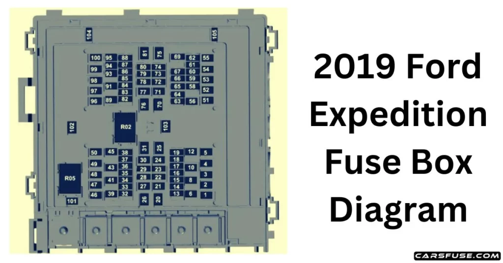
Relay Number
Protected Component
R02
Powertrain Control Module.
R05
Electric fan 2.
Note: The respective vehicle owner's manual will provide you with the most accurate and up-to-date information.It's important to go through owner's manual for the exact location and identification of the fuse box in your vehicle, as the location can vary slightly depending on the trim level or optional features.
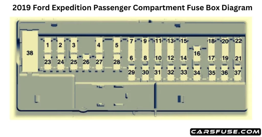
PASSENGER COMPARTMENT FUSE PANEL
2019 FORD EXPEDITION FUSE BOX DIAGRAM
3Micro 2 fuses/ 4Micro 3 fuses.
Fuse or Relay Number
Fuse Rating
Protected Component
1
—
Not used.
2
7.5A 3
Driver seat switch.
3
20A3
Driver door unlock.
4
5A3
Trailer brake controller.
5
20A3
Speaker amplifier.
6
10A4
Not used (spare).
7
10A4
Not used (spare).
8
—
Not used.
9
10A4
Rear seat entertainment module. Head-up display.
10
5A4
Wireless accessory charger module. Hands-free liftgate module. Power liftgate module.
11
5A4
Keypad. Combined sensor module.
12
7.5A4
Cluster. Electronic control panel. Smart datalink connector logic.
13
7.5A4
Gear shift module. Steering column control module.