When faced with electrical problems, the 2018 Ford Expedition fuse box diagram serves as a helpful tool to locate and replace blown fuses accurately.
In this article we will take a deep dive into this invaluable resource. With a exact breakdown of each fuse’s function, we aim to provide you with a comprehensive understanding of how these tiny power guardians contribute to the seamless operation of your vehicle’s electrical components.
Table of Contents
Note: All information contained in this Quick Reference Guide was accurate at the time of duplication. For detailed operating and safety information, please consult your Ford Expedition Owner’s Manual.
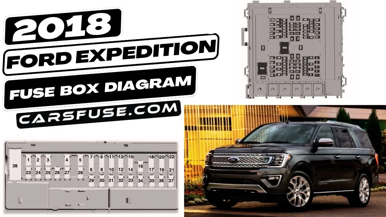
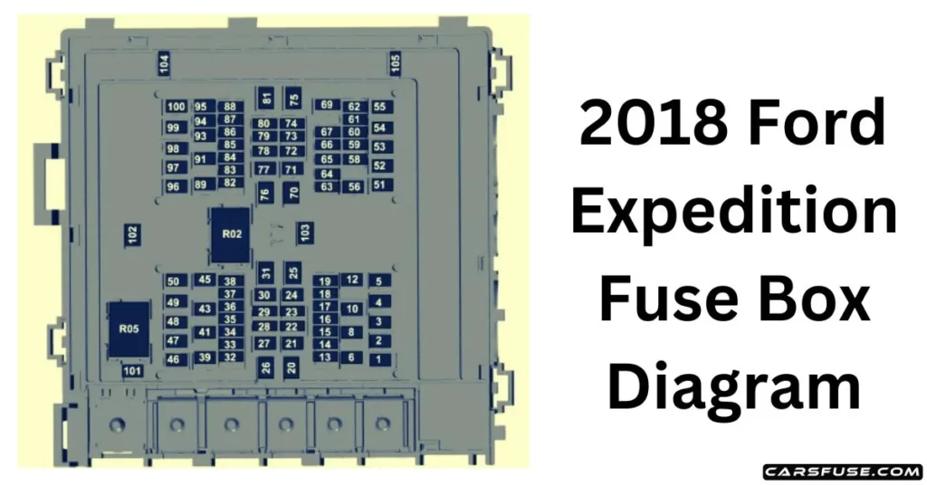
2018 Ford Expedition Fuse Box Diagram
Engine Compartment
2018 FORD EXPEDITION FUSE BOX DIAGRAM
Note: In the event that you need to disconnect and reconnect the battery, it's important to note that certain features may require resetting. This step is necessary to restore their functionality.1Micro fuses / 2M case fuses.
Voltage quality module run/start power. Blindspot information system. Head-Up Display. Image processing module B. Front view camera. Rearview camera. Cruise control module.
16
10A1
Powertrain control module (PCM) run/start feed.
17
10A1
Antilock brake system run/ start feed.
18
10A1
Electronic power assist steering run / start feed.
19
—
Not used.
20
40A2
Front blower.
21
40A2
Passenger seat motors.
22
20A1
Not used.
23
10A1
Alternator A-line.
24
30A2
Trailer brake control module.
25
50A2
Body control module power 1.
26
50A2
Electronic fan 3.
27
40A2
Driver seat motors.
28
15A1
Rear heated seats.
29
10A1
Integrated wheel end solenoid.
30
25A2
Trailer tow class II-IV battery charge.
31
50A2
Power folding seat module.
32
10A1
A/C clutch.
33
—
Not used.
34
—
Not used.
35
20A1
Vehicle power 4.
36
10A1
Vehicle power 3.
37
25A1
Vehicle power 2.
38
25A1
Vehicle power 1.
39
—
Not used.
41
50A2
Inverter.
43
20A2
Trailer Tow Light Module Class II-IV.
45
20A2
Front/rear washer pump.
46
7.5A1
Family entertainment system.
47
—
Not used.
48
—
Not used.
49
—
Not used.
50
30A2
Fuel pump.
51
20A2
Powerpoint 3.
52
50A2
Body control module (BCM) voltage quality module (VQM).
53
25A2
Trailer tow park lamps relay.
54
40A2
Electronic limited-slip differential relay.
55
40A2
AUX blower.
56
20A2
Powerpoint 4.
58
5A1
Not used (spare).
59
—
Not used.
60
5A1
Not used (spare).
61
25A1
Not used (spare).
62
25A1
Not used (spare).
63
25A1
4×4 module.
64
—
Not used.
65
—
Not used.
66
—
Not used.
67
—
Not used.
69
—
Not used.
70
40A2
Anti-lock brake system/ parking brake module.
71
25A2
4×4 module.
72
—
Not used.
73
—
Not used.
74
10A1
Trailer tow backup lamps.
75
—
Not used.
76
50A2
Body control module power 2.
77
30A2
Climate-controlled (Heated/Vented) seat module.
78
20A1
Not used (spare).
79
—
Not used.
80
10A1
Heated wiper park.
81
—
Not used.
82
—
Not used.
83
15A1
Transmission control module power.
84
—
Not used.
85
—
Not used.
86
5A1
USB smart charger 5.
87
5A1
USB smart charger 3.
88
10A1
Multi-contour seat relay.
89
40A2
Power running boards.
91
30A2
Power liftgate module.
93
15A1
Heated mirrors.
94
5A1
USB smart charger 1.
95
10A1
USB smart charger 2.
96
30A2
Rear wiper motor relay.
97
40A2
Intercooler puller relay fan.
98
15A2
Transmission oil pump.
99
40A2
Heated backlite.
100
20A2
Powerpoint 5.
101
25A2
Fan 2.
102
—
Not used.
103
—
Not used.
104
—
Not used.
105
—
Not used.
Relay Number
Protected Component
R02
Electric fan 2.
R05
Powertrain Control Module.
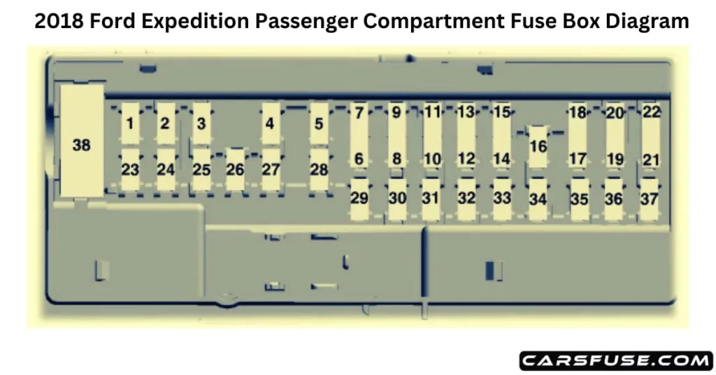
Passenger Compartment Fuse Panel
2018 FORD EXPEDITION FUSE BOX DIAGRAM
3Micro 2 fuses/ 4Micro 3 fuses
Fuse or Relay Number
Fuse Rating
Protected Component
1
—
Not used.
2
7.5A 3
Driver seat switch.
3
20A3
Driver door unlock.
4
5A3
Trailer brake controller.
5
20A3
Speaker amplifier.
6
10A4
Not used (spare).
7
10A4
Not used (spare).
8
—
Not used.
9
10A4
Rear seat entertainment module. Head-up display.
10
5A4
Wireless accessory charger module. Hands-free liftgate module. Power liftgate module.
11
5A4
Keypad. Combined sensor module.
12
7.5A4
Cluster. Electronic control panel. Smart datalink connector logic.
13
7.5A4
Gear shift module. Steering column control module.