In this article, we will find out the intricacies of the 2020 Ford Expedition fuse box diagram, and get to the bottom of the mystery behind the fuses & relays that control the vehicle’s electrical operations. A robust electrical system powers various components and functions. These fuses are designed to prevent damage to sensitive components, such as the engine control module, lights, audio system, and other vital circuits from overloads.
Table of Contents
Note: All information contained in this Quick Reference Guide was accurate at the time of duplication. For detailed operating and safety information, please consult your Ford Expedition Owner’s Manual.
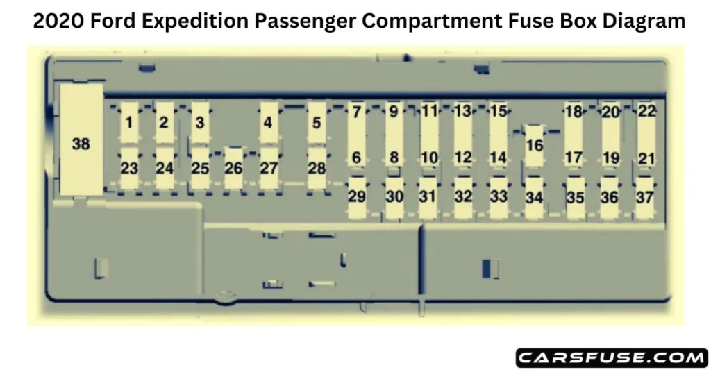
2020 Ford Expedition Fuse Box Diagram
ENGINE COMPARTMENT
2020 FORD EXPEDITION FUSE BOX DIAGRAM
Note: In the event that you need to disconnect and reconnect the battery, it's important to note that certain features may require resetting. This step is necessary to restore their functionality.
Voltage quality module run/start power. Blindspot information system. Image processing module B. Front view camera. Rearview camera. Cruise control module.
16
10A
Powertrain control module run/start feed.
17
10A
Anti-lock brake system run/start feed.
18
10A
Electronic power assist steering run/start feed.
19
—
Not used.
20
40A
Front blower.
21
40A
Passenger seat motors.
22
—
Not used.
23
10A
Alternator A-line.
24
30A
Trailer brake control module.
25
50A
Body control module power 1.
26
50A
Electronic fan 3.
27
40A
Driver seat motors.
28
15A
Rear heated seats. Rear seat climate control module.
29
10A
Integrated wheel end solenoid.
30
25A
Trailer tow class II-IV battery charge.
31
50A
Power folding seat module.
32
10A
A/C clutch.
33
—
Not used.
34
—
Not used.
35
20A
Vehicle power 4.
36
10A
Vehicle power 3.
37
25A
Vehicle power 2.
38
25A
Vehicle power 1.
39
—
Not used.
41
—
Not used.
43
—
Not used.
45
20A
Front and rear washer pump.
46
7.5A
Family entertainment system.
47
—
Not used.
48
—
Not used.
49
—
Not used.
50
30A
Fuel pump.
51
20A
Powerpoint 3.
52
50A
Body control module voltage quality module.
53
25A
Trailer tow park lamps relay. Trailer tow control module.