In this article, we will provide you with an in-depth exploration of the 2017 Ford Expedition fuse box diagram. We’ll explore the complexities and demystify the purpose of each fuse, enabling you to navigate your electrical system with confidence and ease.
Table of Contents
Note: All information contained in this Quick Reference Guide was accurate at the time of duplication. For detailed operating and safety information, please consult your Ford Expedition Owner’s Manual.
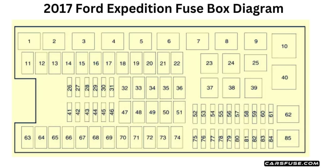
2017 Ford Expedition Fuse Box Diagram
Engine Compartment
Note: In the event that you need to disconnect and reconnect the battery, it's important to note that certain features may require resetting. This step is necessary to restore their functionality.1J Case Low Profile / 2Mini Fuses.
2017 FORD EXPEDITION FUSE BOX DIAGRAM
Fuse or Relay Number
Fuse Amp Rating
Protected Components
1
Relay
Rear washer relay.
2
Relay
Starter relay.
3
Relay
Blower motor relay.
4
Relay
Rear wiper relay.
5
Relay
Fuel pump relay.
6
Relay
Electronic cooling fan.
7
Relay
Rear window defroster. Heated mirror relay.
8
Relay
Electronic cooling fan.
9
Relay
Run/start relay.
10
Relay
Power distribution box relay.
11
40A1
Power running boards. Heated seats.
12
40A1
Run/start relay.
13
30A1
Starter relay.
14
50A1
Electronic cooling fan.
15
—
Not used.
16
50A1
Electronic fan.
17
—
Not used.
18
30A1
Trailer brake.
19
20A1
Powerpoint (console).
20
20A1
4×4 module HAT 2.
21
30A1
Trailer tow module.
22
30A1
Passenger power seat.
23
Relay
Air conditioner clutch relay.
24
Relay
Trailer tow park lamp relay.
25
—
Not used.
26
10A2
ALT sensor.
27
20A2
4×4 module HAT 1.
28
25A2
Trailer tow park lamp relay.
29
10A2
Integrated wheel end solenoid.
30
10A2
Air conditioner clutch relay.
31
15A2
Trailer tow backup lamp.
32
40A1
Blower motor relay.
33
40A1
110-volt AC power point.
34
30A1
Auxiliary blower motor.
35
50A1
Powertrain control module relay.
36
30A1
Power liftgate.
37
—
Not used.
38
—
Not used.
39
Relay
Trailer tow backup lamps relay.
40
Relay
Electronic fan 2 relay.
41
10A2
Powertrain control module keep-alive power.
42
5A2
Run/start relay.
43
10A2
Brake on/off switch.
44
20A2
Fuel pump relay.
45
10A2
Not used (spare).
46
15A2
Front/rear washer pump.
47
30A1
Rear wiper motor.
48
40A1
Trailer tow module.
49
—
Not used.
50
30A1
Front wiper motor relay.
51
40A1
Rear window defroster and heated mirror relay.
52
10A1
Anti-lock brake system run/start feed.
53
5A1
Powertrain control module ISP.
54
5A1
Power steering.
55
—
Not used.
56
30A1
Passenger compartment fuse panel run/start feed.
57
5A2
Blower motor run/start.
58
—
Not used.
59
15A2
Heated mirrors.
60
—
Not used.
61
—
Not used.
62
—
Not used.
63
25A1
Electronic fan.
64
30A1
Moonroof.
65
20A1
Not used (spare).
66
20A1
Auxiliary power point (rear of center console).
67
40A1
Front row climate-controlled seats.
68
30A1
Anti-lock brake system valves.
69
60A1
Anti-lock brake system pump.
70
30A1
Third-row power fold seat.
71
20A1
Auxiliary power point/cigar lighter.
72
20A1
Auxiliary power point (right rear quarter panel).
73
20A1
Rear seat climate module.
74
30A1
Driver power seat.
75
25A2
Vehicle power 1 – powertrain control module.
76
20A2
Vehicle power 2 – powertrain control module.
77
20A2
Vehicle power 4 – ignition coils.
78
—
Not used.
79
15A2
Vehicle power 3 – powertrain control module.
80
—
Not used.
81
—
Not used.
82
5A2
Rain sensor.
83
—
Not used.
84
—
Not used.
85
Relay
Wiper motor relay.
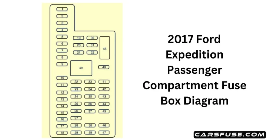
Passenger Compartment Fuse Panel
2017 FORD EXPEDITION FUSE BOX DIAGRAM
Fuse or Relay Number
Fuse Amp Rating
Protected Components
1
30A
Driver window.
2
15A
Rear seat control. Multimedia gateway module.
3
30A
Passenger window.
4
10A
Demand lamps.
5
20A
Amplifier.
6
5A
Rear electronic automatic temperature control.
7
7.5A
Power mirror. Driver seat memory switch.
8
—
Not used.
9
10A
SYNC. Power lift gate. Electric finish panel. Display.
10
10A
Run accessory relay.
11
10A
Passive entry/start module.
12
15A
Interior lighting. Puddle lamps.
13
15A
Right turn and stop/turn signals.
14
15A
Left turn and stop/turn signals.
15
15A
Reverse lamp. Center high-mount stop lamp. EC mirror.