
In this article, we present a comprehensive guide to the 2016 Ford Expedition Fuse Box Diagram covering the layout of the fuse box, discuss the purpose of different fuses and relays, and offer practical insights on troubleshooting common electrical problems.
Whether you are a mechanic, or a inquisitive owner, this guide will equip you with the knowledge needed to effectively navigate your Expedition’s electrical system.
Table of Contents
Note: All information contained in this Quick Reference Guide was accurate at the time of duplication. For detailed operating and safety information, please consult your Ford Expedition Owner’s Manual.
2016 Ford Expedition Fuse Box Diagram
ENGINE COMPARTMENT
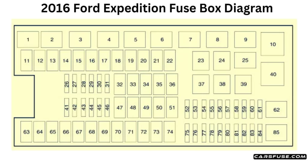
Note: In the event that you need to disconnect and reconnect the battery, it's important to note that certain features may require resetting. This step is necessary to restore their functionality.
1J Case Low Profile /  2Mini Fuses.
| Fuse or Relay Number | Fuse Amp Rating | Protected Components |
| 1 | Relay | Rear washer relay. |
| 2 | Relay | Starter relay. |
| 3 | Relay | Blower motor relay. |
| 4 | Relay | Rear wiper relay. |
| 5 | Relay | Fuel pump relay. |
| 6 | Relay | Electronic cooling fan. |
| 7 | Relay | Rear window defroster. Heated mirror relay. |
| 8 | Relay | Electronic cooling fan. |
| 9 | Relay | Run/start relay. |
| 10 | Relay | Power distribution box relay. |
| 11 | 40A1 | Power running boards. Heated seats. |
| 12 | 40A1 | Run/start relay. |
| 13 | 30A1 | Starter relay. |
| 14 | 50A1 | Electronic cooling fan. |
| 15 | — | Not used. |
| 16 | 50A1 | Electronic fan. |
| 17 | — | Not used. |
| 18 | 30A1 | Trailer brake. |
| 19 | 20A1 | Powerpoint (console). |
| 20 | 20A1 | 4×4 module HAT 2. |
| 21 | 30A1 | Trailer tow module. |
| 22 | 30A1 | Passenger power seat. |
| 23 | Relay | Air conditioner clutch relay. |
| 24 | Relay | Trailer tow park lamp relay. |
| 25 | — | Not used. |
| 26 | 10A2 | ALT sensor. |
| 27 | 20A2 | 4×4 module HAT 1. |
| 28 | 25A2 | Trailer tow park lamp relay. |
| 29 | 10A2 | Integrated wheel end solenoid. |
| 30 | 10A2 | Air conditioner clutch relay. |
| 31 | 15A2 | Trailer tow backup lamp. |
| 32 | 40A1 | Blower motor relay. |
| 33 | 40A1 | 110-volt AC power point. |
| 34 | 30A1 | Auxiliary blower motor. |
| 35 | 50A1 | Powertrain control module relay. |
| 36 | 30A1 | Power liftgate. |
| 37 | — | Not used. |
| 38 | — | Not used. |
| 39 | Relay | Trailer tow backup lamps relay. |
| 40 | Relay | Electronic fan 2 relay. |
| 41 | 10A2 | Powertrain control module keep-alive power. |
| 42 | 5A2 | Run/start relay. |
| 43 | 10A2 | Brake on/off switch. |
| 44 | 20A2 | Fuel pump relay. |
| 45 | 10A2 | Not used (spare). |
| 46 | 15A2 | Front/rear washer pump. |
| 47 | 30A1 | Rear wiper motor. |
| 48 | 40A1 | Trailer tow module. |
| 49 | — | Not used. |
| 50 | 30A1 | Front wiper motor relay. |
| 51 | 40A1 | Rear window defroster and heated mirror relay. |
| 52 | 10A1 | Anti-lock brake system run/start feed. |
| 53 | 5A1 | Powertrain control module ISP. |
| 54 | 5A1 | Power steering. |
| 55 | — | Not used. |
| 56 | 30A1 | Passenger compartment fuse panel run/start feed. |
| 57 | 5A2 | Blower motor run/start. |
| 58 | — | Not used. |
| 59 | 15A2 | Heated mirrors. |
| 60 | — | Not used. |
| 61 | — | Not used. |
| 62 | — | Not used. |
| 63 | 25A1 | Electronic fan. |
| 64 | 30A1 | Moonroof. |
| 65 | 20A1 | Not used (spare). |
| 66 | 20A1 | Auxiliary power point (rear of center console). |
| 67 | 40A1 | Front row climate-controlled seats. |
| 68 | 30A1 | Anti-lock brake system valves. |
| 69 | 60A1 | Anti-lock brake system pump. |
| 70 | 30A1 | Third-row power fold seat. |
| 71 | 20A1 | Auxiliary power point/cigar lighter. |
| 72 | 20A1 | Auxiliary power point (right rear quarter panel). |
| 73 | 20A1 | Rear seat climate module. |
| 74 | 30A1 | Driver power seat. |
| 75 | 25A2 | Vehicle power 1 – powertrain control module. |
| 76 | 20A2 | Vehicle power 2 – powertrain control module. |
| 77 | 20A2 | Vehicle power 4 – ignition coils. |
| 78 | — | Not used. |
| 79 | 15A2 | Vehicle power 3 – powertrain control module. |
| 80 | — | Not used. |
| 81 | — | Not used. |
| 82 | 5A2 | Rain sensor. |
| 83 | — | Not used. |
| 84 | — | Not used. |
| 85 | Relay | Wiper motor relay. |
PASSENGER COMPARTMENT FUSE PANEL
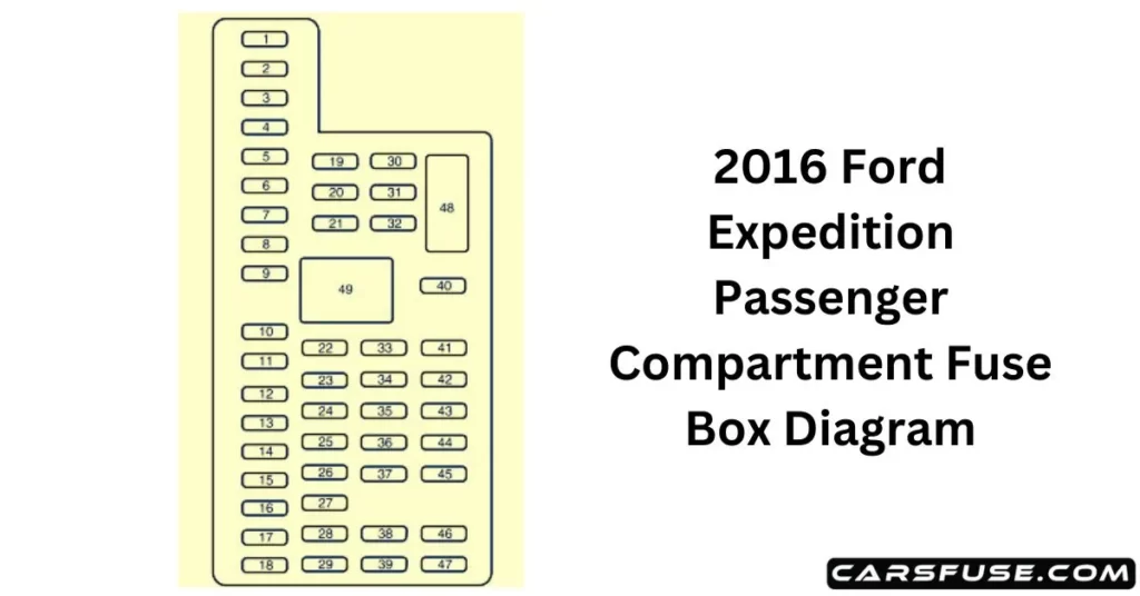
| Fuse or Relay Number | Fuse Amp Rating | Protected Components |
| 1 | 30A | Driver window. |
| 2 | 15A | Rear seat control. Multimedia gateway module. |
| 3 | 30A | Passenger window. |
| 4 | 10A | Demand lamps. |
| 5 | 20A | Amplifier. |
| 6 | 5A | Rear electronic automatic temperature control. |
| 7 | 7.5A | Power mirror. Driver seat memory switch. |
| 8 | — | Not used. |
| 9 | 10A | SYNC. Power lift gate. Electric finish panel. Display. |
| 10 | 10A | Run accessory relay. |
| 11 | 10A | Passive entry/start module. |
| 12 | 15A | Interior lighting. Puddle lamps. |
| 13 | 15A | Right turn and stop/turn signals. |
| 14 | 15A | Left turn and stop/turn signals. |
| 15 | 15A | Reverse lamp. Center high-mount stop lamp. EC mirror. |
| 16 | 10A | Right front low beam. |
| 17 | 10A | Left front low beam. |
| 18 | 10A | Brake shift interlock/start button LED/keypad illumination. Third-row power folding seat. Passive entry touch start. |
| 19 | — | Not used. |
| 20 | 20A | Lock/unlock relays. |
| 21 | — | Not used. |
| 22 | 20A | Horn. |
| 23 | 15A | Steering wheel control module. Cluster. |
| 24 | 15A | Adjustable pedals/power adjustable column. Datalink. |
| 25 | 15A | Liftgate release decklid. Liftglass release motor. |
| 26 | 5A | Push to start switch. |
| 27 | 20A | Passive entry/start module. |
| 28 | 15A | Ignition switch. Key inhibit switch. |
| 29 | 20A | Radio. GPS. |
| 30 | 15A | Front park lamps. |
| 31 | 5A | Trailer brake on/off. |
| 32 | 15A | Power vent. Driver’s window motor. Power inverter. |
| 33 | 10A | CCD suspension module. |
| 34 | 10A | Rear park assist. Rear camera. BLIS. Heated seat. |
| 35 | 5A | Climate module. O/D switch. |
| 36 | — | Not used. |
| 37 | 10A | 4X4 module. |
| 38 | 10A | EC mirror. Moonroof. DVD. AM/FM radio. |
| 39 | 15A | Left and right front high beams. |
| 40 | 10A | Rear park/tail lamps. |
| 41 | 7.5A | Restraints control module. |
| 42 | — | Not used. |
| 43 | — | Not used. |
| 44 | — | Not used. |
| 45 | 5A | Not used (spare). |
| 46 | 10A | Climate control. |
| 47 | 15A | Fog lamps. |
| 48 | 30A | Front passenger and rear windows circuit breaker. |
| 49 | Relay | Windows and vents relay. |
