In this article, with an in-depth exploration of the 2009 Ford Expedition fuse box diagram, offer a comprehensive guide that will empower owners to find out the vehicle’s electrical components.
We’ll expore the complexities and demystify the purpose of each fuse, enabling you to navigate your Ford Expedition’s electrical system with confidence and ease.
Table of Contents
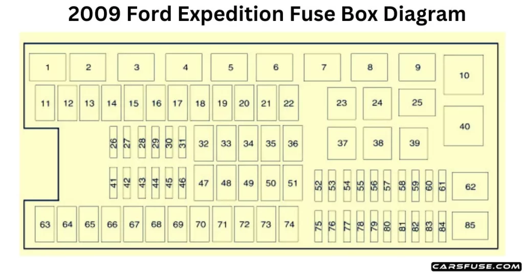
2009 Ford Expedition Fuse Box Diagram
POWER DISTRIBUTION BOX
2009 FORD EXPEDITION FUSE BOX DIAGRAM
* Mini Fuses/ ** Cartridge Fuses
Fuse/RelayLocation
Fuse AmpRating
Protected Circuits
1
—
Powertrain Control Module power relay
2
—
Starter relay
3
—
Not used
4
—
Trailer tow relay
5
—
Fuel pump relay
6
—
Trailer tow park lamp relay
7
—
Heated backlite/Mirror relay
8
—
Not used
9
—
Run/Start (R/S) relay
10
—
Rear air suspension (RAS) relay
11
40A**
Power running board motors
12
40A**
Run/Start relay
13
30A **
Starter relay
14
—
Not used
15
—
Not used
16
—
Not used
17
—
Not used
18
30A**
Trailer brake
19
60A**
Rear air suspension relay feed
20
20A**
4×4 module
21
30A**
Trailer tow battery charge
22
30A**
Passenger power seat
23
—
A/C clutch relay
24
—
Not used
25
—
Not used
26
15A*
Transmission Control Module (TCM) power
27
20A*
4×4
28
25A*
Trailer tow park lamp relay feed
29
20A*
Back up lamps, Integrated wheel end solenoid
30
10A*
A/C clutch
31
—
Not used
32
40A**
Blower motor relay feed
33
—
Not used
34
30A**
Auxiliary blower motor
35
30A**
Powertrain Control Module (PCM) relay
36
30A**
Power liftgate
37
—
Trailer tow left-hand stop/turn relay
38
—
Trailer tow right-hand stop/turn relay
39
—
Backup lamps relay
40
—
Blower motor relay
41
10A*
TCM/PCM keep alive power
42
—
Not used
43
15A*
Brake on/off switch
44
20A*
Fuel pump relay
45
25A*
Trailer tow stop turn relay feed
46
—
Not used
47
—
Not used
48
30A**
Rear air suspension module
49
—
Not used
50
30A**
Front wiper motor
51
40A**
Heated backlite/mirror relay
52
10A*
Anti-lock Brake System (ABS) R/S feed
53
10A*
Rear air suspension module R/S feed
54
5A*
TCM R/S power
55
5A*
Fuel pump relay R/S feed
56
30A*
SPJB R/S feed
57
10A*
Blower motor R/S feed
58
15A*
Trailer tow backup lamps
59
15A*
Heated mirrors
60
—
One-touch Start diode
61
—
Fuel pump diode
62
—
Not used
63
—
Not used
64
30A**
Moon roof
65
20A**
Auxiliary power point
66
20A**
Auxiliary power point
67
40A**
Climate controlled seats
68
60A**
ABS valves
69
60A**
ABS pump
70
40A**
Left-hand and right-hand third-row power fold seat