In this article, we’re here to help you make sense of the 2008 Ford Expedition fuse box diagram and deep dive into this invaluable resource. Explaining the functions of each fuse, to make it easier for you to understand your vehicle’s electrical system, and empowering you with the knowledge to troubleshoot electrical issues like a pro.
Table of Contents
Note: All information contained in this Quick Reference Guide was accurate at the time of duplication. For detailed operating and safety information, please consult your Owner’s Manual.
The electrical system of your vehicle is an important component that powers various functions, ensuring a smooth and efficient driving experience. The fuse box serves as a guardian, safeguarding the multitude of electrical components within your SUV from potential harm or malfunctions. By carefully distributing electrical currents, the fuse box prevents overloads and shorts, preserving the integrity of crucial components such as lights, wipers, radio, and more.
A detailed and easy-to-follow fuse box diagram is the key to unlocking this intricate electrical puzzle. It provides a roadmap, allowing you to identify and locate specific fuses, understands their respective amperage ratings, and determine their corresponding circuits.
As a vehicle owner, it’s important for you to understand the significance of a fuse box and its diagram in your vehicle. Let’s break it down:
- Protecting the electrical system: A fuse box is responsible for safeguarding the electrical system of your car.
- Preventing electrical failures: Each fuse in the fuse box is assigned to a specific electrical circuit in your car, such as the headlights, windshield wipers, radio, or power windows.
- Quick identification and replacement: The fuse box diagram provides a visual representation of the fuse box and indicates which fuse corresponds to each electrical circuit.
- Basic troubleshooting: Understanding the fuse box and its diagram allows you to perform basic troubleshooting on electrical issues.
- Emergency situations: In rare cases, certain electrical malfunctions can pose safety risks, such as a faulty brake light or a non-functioning horn.
Note: Always disconnect the battery before servicing high current fuses. To reduce risk of electrical shock, always replace the cover to the Power Distribution Box, and Auxiliary Relay Box before reconnecting the battery or refilling fluid reservoirs.
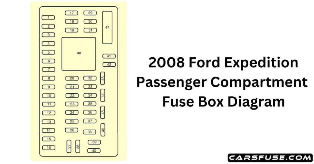
2008 Ford Expedition Power distribution box
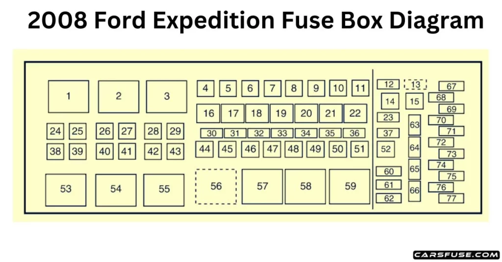
Located within the engine compartment of your vehicle, you will find the power distribution box, which serves as a protective enclosure for high-current fuses. In the power distribution box in the engine compartment, the manufacturer has taken proactive measures to enhance the reliability of your vehicle’s electrical components. The main electrical systems are adequately protected, allowing for a smooth and trouble-free operation of your vehicle. With the coding system, you can effectively troubleshoot and address any issues related to the high-current fuses within the power distribution box. The high-current fuses are coded as follows:
Note: In the event that you need to disconnect and reconnect the battery, it's important to note that certain features may require resetting. This step is necessary to restore their functionality.

* Mini Fuses/ ** Cartridge Fuses
Fuse/RelayLocation | FuseAmpRating | Power Distribution Box Description |
1 | — | Blower relay |
2 | — | Not used |
3 | — | Rear window defroster relay |
4 | 30A** | Third-row seats (driver side) |
5 | 30A ** | Trailer tow connector (electric brake) |
6 | 60A** | ABS (valves) |
7 | — | Not used |
8 | 40A** | Heated/cooled seats |
9 | 60A** | ABS (pump) |
10 | 20A** | Rear console powerpoint |
11 | 30A** | Auxiliary blower |
12 | 25A* | Trailer tow connector (park lamps) |
13 | 30A * | Trailer tow connector (battery charge) |
14 | — | Not used |
15 | — | Not used |
16 | — | A/C clutch relay |
17 | — | Not used |
18 | — | Fuel pump relay |
19 | — | Back-up relay |
20 | — | Trailer tow connector relay (left turn signal) |
21 | — | Trailer tow connector relay (right turn signal) |
22 | — | Not used |
23 | 15A* | Heated mirrors |
24 | 40A** | Blower motor |
25 | — | Not used |
26 | — | Not used |
27 | 30A** | Power liftgate |
28 | 40A** | Rear window defroster, Heated mirror |
29 | 30A** | Passenger seat |
30 | 10A* | A/C clutch |
31 | 15A* | Brake lamps |
32 | 20A* | Fuel pump |
33 | 20A* | Back-up lamps |
34 | 25A* | Trailer tow connector (stop/turn lamps) |
35 | 20A* | 4×4 module |
36 | 10A* | Powertrain Control Module (PCM) – Keep alive power, Canister vent |
37 | 15A* | Transmission B+ |
38 | 30A** | Third-row seats (passenger side) |
39 | 60A** | Air suspension pump |
40 | 30A** | Starter motor |
41 | 20A** | IP/Console powerpoint |
42 | — | Not used |
43 | 20A** | 4×4 module motor |
44 | — | Not used |
45 | 30A** | Driver seat |
46 | 40A** | Run/Start bus bar |
47 | 30A** | Air suspension – solenoids |
48 | — | Not used |
49 | 30A** | Front wipers/washer |
50 | 30A** | PCM – bus bar |
51 | 20A** | Cargo powerpoint |
52 | 20A** | Cigarette lighter |
53 | — | Air suspension relay |
54 | — | Starter relay |
55 | — | Trailer tow connector relay (park lamp) |
56 | — | Trailer tow connector relay (battery charge) |
57 | — | Run/Start relay |
58 | — | Not used |
59 | — | PCM relay |
60 | — | One-touch Start diode |
61 | — | Not used |
62 | — | Fuel pump diode |
63 | 15A* | Trailer tow connector (backup lamp) |
64 | — | Not used |
65 | 10A* | Air suspension logic |
66 | — | Not used |
67 | 10A* | Blower coil |
68 | — | Not used |
69 | 30A* | Run/Start – passenger compartment fuse panel |
70 | 20A* | PCM (sensors) – EFC, A/C clutch coil |
71 | 5A* | Fuel coil, ISP-R |
72 | 20A* | PCM (ignition coils) |
73 | 5A* | Transmission ignition |
74 | 20A* | PCM (sensors) – HEGO/CMS, MAFS, EVMV, CMCV, Speed deactivation switch, VCT |
75 | 5A* | 4×4 Integrated Wheel Ends (IWE) solenoid |
76 | 20A* | PCM – VPWR |
77 | 10A* | ABS logic, Heated PCV |
2008 Ford Expedition Passenger compartment fuse panel
The interior fuse box of your vehicle is conveniently situated within the passenger footwell, specifically on the right-hand side. It remains concealed behind a well-designed trim panel, providing easy access for inspection and replacement of fuses whenever necessary. This advantageous placement allows you to ensure the uninterrupted functionality of your vehicle’s electrical systems, maintaining a smooth and efficient operation. By conveniently locating the fuse panel within the passenger compartment, the manufacturer has made it effortless for you to address any fuse-related issues, promoting a hassle-free experience with your vehicle.

Fuse/RelayLocation | Fuse AmpRating | Passenger Compartment FusePanel Description |
1 | 30A | Smart window #1 |
2 | 15A | Driver-side memory module |
3 | 15A | FES, Audio rear seat controls, SDARS |
4 | 30A | Smart window #2 |
5 | 10A | Keypad illumination, 3rd row seat enable, Brake Shift Interlock(BSI), SPDJB |
6 | 20A | Turn signals |
7 | 10A | Low beam headlamps (left) |
8 | 10A | Low beam headlamps (right) |
9 | 15A | Interior lights |
10 | 15A | Backlighting, Puddle lamps |
11 | 10A | Not used (Spare) |
12 | 7.5A | Power mirror switch, Driver seat memory switch |
13 | 7.5A | Not used (Spare) |
14 | 10A | Power liftgate module – keep-alive power |
15 | 10A | Climate control |
16 | 15A | Not used (Spare) |
17 | 20A | All lock motor feeds, Liftgate release, Liftglass release |
18 | 20A | Not used (Spare) |
19 | 25A | Rear wiper |
20 | 15A | Adjustable pedals, Datalink |
21 | 15A | Fog lamps, Cornering lamps |
22 | 15A | Park lamps relay |
23 | 15A | High beam headlamps |
24 | 20A | Horn relay |
25 | 10A | Demand lamps, Glovebox, Visor |
26 | 10A | Instrument panel cluster |
27 | 20A | Ignition switch |
28 | 5A | Radio |
29 | 5A | Instrument panel cluster |
30 | 5A | Not used (Spare) |
31 | 10A | Compass, Automatic dimming rear view mirror |
32 | 10A | Restraints control module |
33 | 10A | Not used (Spare) |
34 | 5A | Not used (Spare) |
35 | 10A | Rear park assist, 4×4, rear video camera |
36 | 5A | PATS transceiver |
37 | 10A | Climate control |
38 | 20A | Subwoofer/Amp (Audiophile radio) |
39 | 20A | Radio |
40 | 20A | Not used (Spare) |
41 | 15A | Not used (Spare) |
42 | 10A | Trailer tow battery charge coil |
43 | 10A | Rear wiper logic |
44 | 10A | Not used (Spare) |
45 | 5A | Front wiper logic |
46 | 7.5A | Climate control, Auxiliary relay control |
47 | 30A CircuitBreaker | Power windows, Moon roof |
48 | — | Delayed accessory relay |
2008 Ford Expedition Standard fuse amperage rating and color
Fuse rating | Mini fuses | Standard fuses | Maxi fuses | Cartridge maxi fuses | Fuse link cartridge |
2A | Grey | Grey | — | — | — |
3A | Violet | Violet | — | — | — |
4A | Pink | Pink | — | — | — |
5A | Tan | Tan | — | — | — |
7.5A | Brown | Brown | — | — | — |
10A | Red | Red | — | — | — |
15A | Blue | Blue | — | — | — |
20A | Yellow | Yellow | Yellow | Blue | Blue |
25A | Natural | Natural | — | — | — |
30A | Green | Green | Green | Pink | Pink |
40A | — | — | Orange | Green | Green |
50A | — | — | Red | Red | Red |
60A | — | — | Blue | Yellow | Yellow |
70A | — | — | Tan | — | Brown |
80A | — | — | Natural | Black | Black |
Explore more: 2023 Ford Expedition Fuse Box Diagram. 2022 Ford Expedition Fuse Box Diagram. 2021 Ford Expedition Fuse Box Diagram. 2020 Ford Expedition Fuse Box Diagram. 2019 Ford Expedition Fuse Box Diagram. 2018 Ford Expedition Fuse Box Diagram. 2017 Ford Expedition Fuse Box Diagram. 2016 Ford Expedition Fuse Box Diagram. 2015 Ford Expedition Fuse Box Diagram. 2014 Ford Expedition Fuse Box Diagram. 2013 Ford Expedition Fuse Box Diagram. 2012 Ford Expedition Fuse Box Diagram. 2011 Ford Expedition Fuse Box Diagram. 2010 Ford Expedition Fuse Box Diagram. 2009 Ford Expedition Fuse Box Diagram. 2007 Ford Expedition Fuse Box Diagram. 2006 Ford Expedition Fuse Box Diagram. 2005 Ford Expedition Fuse Box Diagram. 2004 Ford Expedition Fuse Box Diagram. 2003 Ford Expedition Fuse Box Diagram. 2002 Ford Expedition Fuse Box Diagram. 2001 Ford Expedition Fuse Box Diagram. 2000 Ford Expedition Fuse Box Diagram. 1999 Ford Expedition Fuse Box Diagram. 1998 Ford Expedition Fuse Box Diagram. 1997 Ford Expedition Fuse Box Diagram.
Conclusion
In conclusion, understanding the fuse box diagram of your 2008 Ford Expedition is of utmost importance for several reasons. Firstly, it allows you to identify and locate specific fuses that correspond to various electrical components in your vehicle.
Furthermore, having a clear understanding of the fuse box diagram promotes safety. By knowing which fuses protect certain systems, you can quickly address any potential overloads or malfunctions. This empowers you to take appropriate actions and prevent further damage to your vehicle’s electrical systems.
Lastly, it is also important to acknowledge the value of seeking help from experts when needed. While you can handle minor electrical repairs and fuse replacements with confidence, some complex issues may require professional assistance.