In this article, we will find out the significance of the 2010 Ford Expedition fuse box diagram, exploring its details and equipping you with the knowledge necessary to navigate this essential corresponding diagram hold paramount importance of your vehicle’s electrical system.
Table of Contents
Note: All information contained in this Quick Reference Guide was accurate at the time of duplication. For detailed operating and safety information, please consult your Ford Expedition Owner’s Manual.
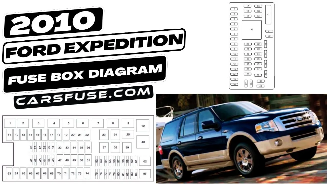
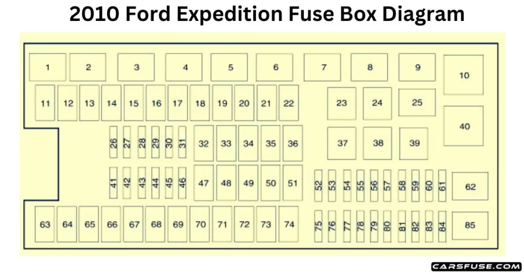
2010 Ford Expedition Fuse Box Diagram
Power distribution box
2010 FORD EXPEDITION FUSE BOX DIAGRAM
* Mini Fuses/ ** Cartridge Fuses
Fuse/RelayLocation
Fuse AmpRating
Protected Circuits
1
—
Powertrain control module(PCM) relay
2
—
Starter relay
3
—
Blower motor relay
4
—
Trailer tow battery charge relay
5
—
Fuel pump relay
6
—
Electronic fan 1 relay
7
—
Rear window defroster/heated mirror relay
8
—
Electronic fan 3 relay
9
—
Run/Start (R/S) relay
10
—
Rear air suspension (RAS) relay
11
40A**
Power running board
12
40A**
R/S relay
13
30A **
Starter relay
14
40A**
Electronic fan
15
—
Not used
16
40A**
Electronic fan
17
—
Not used
18
30A**
Trailer brake
19
60A**
RAS relay feed
20
20A**
4×4 module
21
30A**
Trailer tow battery charge
22
30A**
Passenger power seat
23
—
A/C clutch relay
24
—
Trailer tow park lamp relay
25
—
Not used
26
15A*
Transmission control module(TCM) keep-alive power
27
20A*
4×4
28
25A*
Trailer tow park lamp relay
29
20A*
Backup lamps, Integrated wheel end solenoid
30
10A*
A/C clutch relay
31
—
Not used
32
40A**
Blower motor relay
33
—
Not used
34
30A**
Auxiliary blower motor
35
30A**
PCM relay
36
30A**
Power liftgate
37
—
Trailer tow left hand stop/turn relay
38
—
Trailer tow right hand stop/turn relay
39
—
Backup lamps relay
40
—
Electronic fan 2 relay
41
10A*
PCM keep-alive power
42
—
Not used
43
5A*
Brake on/off switch
44
20A*
Fuel pump relay
45
25A*
Trailer tow stop/turn lamps relay
46
—
Not used
47
—
Not used
48
30A**
RAS module
49
—
Not used
50
30A**
Front wiper motor
51
40A**
Rear window defroster/heated mirror relay
52
10A*
Anti-lock brake system (ABS)R/S feed
53
10A*
RAS module
54
5A*
TCM R/S feed
55
5A*
Fuel pump relay coil R/S feed
56
30A*
Passenger compartment fuse panel R/S feed
57
10A*
Blower motor R/S feed
58
15A*
Trailer tow backup lamps
59
15A*
Heated mirrors
60
—
One-touch start diode
61
—
Fuel pump diode
62
—
Not used
63
25A**
Electronic fan
64
30A**
Moon roof
65
20A**
Auxiliary power point 2
66
20A**
Auxiliary power point 3
67
40A**
Climate controlled seats
68
60A**
ABS valves
69
60A**
ABS pump
70
40A**
Third-row power fold seat
71
20A**
Auxiliary power point/cigar lighter
72
20A**
Auxiliary power point 4
73
—
Not used
74
30A**
Driver power seat
75
20A*
Vehicle power 1 – PCM
76
20A*
Vehicle power 2 – PCM
77
15A*
Vehicle power 4 – ignition coils
78
—
Not used
79
20A*
Vehicle power 3 – PCM
80
—
Not used
81
—
Not used
82
—
Not used
83
—
Not used
84
—
Not used
85
—
Wiper motor relay
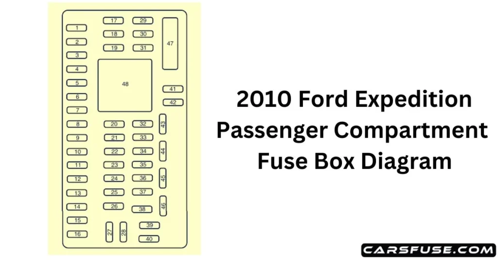
Passenger Compartment Fuse Panel Diagram
The fuse panel is on the right-hand side of the passenger footwell behind a trim panel. To remove the fuse panel cover, press the tabs on both sides of the cover, and then pull it off. To reinstall the fuse panel cover, place the top part of the cover on the fuse panel and push the bottom part until it latches. Gently pull on the cover to make sure it has latched properly.
2010 FORD EXPEDITION FUSE BOX DIAGRAM
Fuse/RelayLocation
Fuse AmpRating
Protected Circuits
1
30A
Smart window #1
2
15A
Driver side memory module
3
15A
Family entertainment system,Audio rear seat controls, Satellite radio, SYNC