This article aims to provide a comprehensive overview on the 2007 Ford Expedition fuse box diagram, explaining the purpose of each fuse and its corresponding electrical circuit. With a meticulous breakdown of each fuse’s function, we aim to provide you with a comprehensive understanding of how these tiny power guardians contribute to the seamless operation of your vehicle’s electrical components.
Table of Contents
Note: All information contained in this Quick Reference Guide was accurate at the time of duplication. For detailed operating and safety information, please consult your Ford Expedition Owner’s Manual.
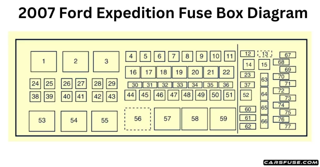
2007 Ford Expedition Fuse Box Diagram (Power Distribution Box)
2007 FORD EXPEDITION FUSE BOX DIAGRAM
* Mini Fuses/ ** Cartridge Fuses
Fuse/RelayLocation
Fuse AmpRating
Power Distribution BoxDescription
1
—
Blower relay
2
—
Not used
3
—
Rear window defroster relay
4
30A**
Third-row seats (driver side)
5
40A**
Trailer tow connector (electric brake)
6
60A**
ABS (valves)
7
—
Not used
8
40A**
Heated/cooled seats
9
60A**
ABS (pump)
10
20A**
Rear console powerpoint
11
30A**
Auxiliary blower
12
25A*
Trailer tow connector (park lamps)
13
30A *
Trailer tow connector (battery charge)
14
—
Not used
15
—
Not used
16
—
A/C clutch relay
17
—
Not used
18
—
Fuel pump relay
19
—
Back-up relay
20
—
Trailer tow connector relay (left turn signal)
21
—
Trailer tow connector relay (right turn signal)
22
—
Not used
23
15A*
Heated mirrors
24
40A**
Blower motor
25
—
Not used
26
—
Not used
27
30A**
Power liftgate
28
40A**
Rear window defroster, Heated mirror
29
30A**
Passenger seat
30
10A*
A/C clutch
31
15A*
Brake lamps
32
20A*
Fuel pump
33
20A*
Back-up lamps
34
25A*
Trailer tow connector (stop/turn lamps)
35
20A*
4×4 module
36
10A*
Powertrain Control Module(PCM) – Keep alive power, Canister vent