
In this article, we will provide you with an in-depth exploration of the 2000 Ford Expedition fuse box diagram. We’ll unravel the complexities and demystify the purpose of each fuse, enabling you to navigate your electrical system with confidence and ease.
Table of Contents
Note: All information contained in this Quick Reference Guide was accurate at the time of duplication. For detailed operating and safety information, please consult your Ford Expedition Owner’s Manual.
2000 Ford Expedition Fuse Box Diagram Chart (Power distribution box)
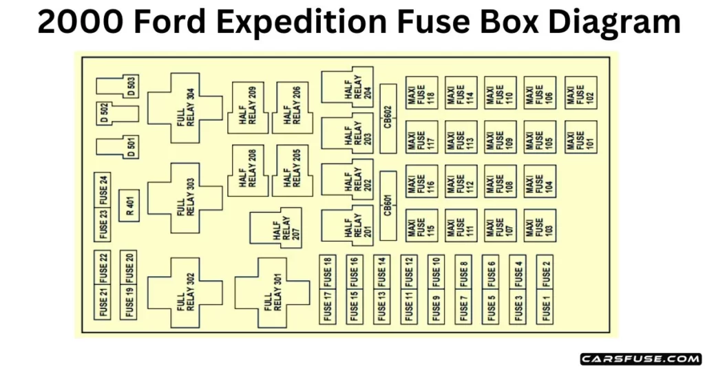
Note: In the event that you need to disconnect and reconnect the battery, it's important to note that certain features may require resetting. This step is necessary to restore their functionality.

*Mini fuses / **Maxi fuses
| Fuse/Relay Location | Fuse AmpRating | Power Distribution Box Description |
| 1 | 20A * | PowerPoint |
| 2 | 30A* | Powertrain Control Module |
| 3 | 30A* | Headlamps/Autolamps |
| 4 | — | Not Used |
| 5 | 20A* | Trailer Tow Backup/Park Lamps |
| 6 | 15A* | Parklamps/Autolamps, Passenger Fuse Panel Feed Fuse #18 |
| 7 | 20A* | Horn |
| 8 | 15A* | Power Door Locks |
| 9 | 15A* | Daytime Running Lamps (DRL), Fog Lamps |
| 10 | 20A* | Fuel Pump |
| 11 | 20A* | Alternator Field |
| 12 | 20A* | Rear Auxiliary PowerPoint |
| 13 | 15A* | A/C Clutch |
| 14 | — | Not Used |
| 15 | — | Not Used |
| 16 | — | Not Used |
| 17 | — | Not Used |
| 18 | 15A* | Powertrain Control Module, FuelInjectors, Fuel Pump Relay, Idle AirControl, Mass Air Flow Sensor |
| 19 | 10A* | Trailer Tow Stop and Right Turn Lamp |
| 20 | 10A* | Trailer Tow Stop and Left Turn Lamp |
| 21 | — | Not Used |
| 22 | — | Not Used |
| 23 | 15A* | HEGO Sensor, Canister Vent, Automatic Transmission, CMS Sensor |
| 24 | — | Not Used |
| 101 | 30A** | Trailer Tow Battery Charge |
| 102 | 50/20A** | Four Wheel Antilock BrakeModule/Rear Wheel Antilock BrakeModule |
| 103 | 50A** | Junction Block Battery Feed |
| 104 | 30A** | 4×4 Shift Motor & Clutch |
| 105 | 40A** | Climate Control Front Blower |
| 106 | 20A** | Inter Cooler Pump (Lightning only) |
| 107 | — | Not Used |
| 108 | 30A** | Trailer Tow Electric Brake |
| 109 | — | Not Used |
| 110 | 30A** | Power Windows |
| 111 | 40A** | Ignition Switch Battery Feed (Start and Run Circuits) |
| 112 | 30A** | Drivers Power Seat, Adjustable Pedals |
| 113 | 40A** | Ignition Switch Battery Feed (Run and Accessory Circuits) |
| 114 | — | Not Used |
| 115 | 20A** | Power Door Locks (SuperCrew only) |
| 116 | — | Not Used |
| 117 | — | Not Used |
| 118 | — | Not Used |
| 201 | — | Trailer Tow Park Lamp Relay |
| 202 | — | Front Wiper Run/Park Relay |
| 203 | — | Trailer Tow Backup Lamp Relay |
| 204 | — | A/C Clutch Relay |
| 205 | — | Horn Relay |
| 206 | — | Fog Lamp Relay |
| 207 | — | Front Washer Pump Relay |
| 208 | — | Inter Cooler Pump Relay (Lightning only) |
| 209 | — | Front Wiper Hi/Lo Relay |
| 301 | — | Fuel Pump Relay |
| 302 | — | Trailer Tow Battery Charge Relay |
| 303 | — | Not Used |
| 304 | — | Powertrain Control Module Relay |
| 305 | — | Fuel Pump Hi/Lo Relay (Lightning only) |
| 306 | — | Inertia Switch Relay (Lightning only) |
| 401 | — | Not Used |
| 501 | — | Powertrain Control Module Diode |
| 502 | — | A/C Compressor Diode |
| 503 | — | Not Used |
| 601 | CB | Power Windows, Moonroof (SuperCrew only) |
| 602 | — | Not Used |
2000 Ford Expedition Fuse Box Diagram Chart (Passenger Compartment Panel)
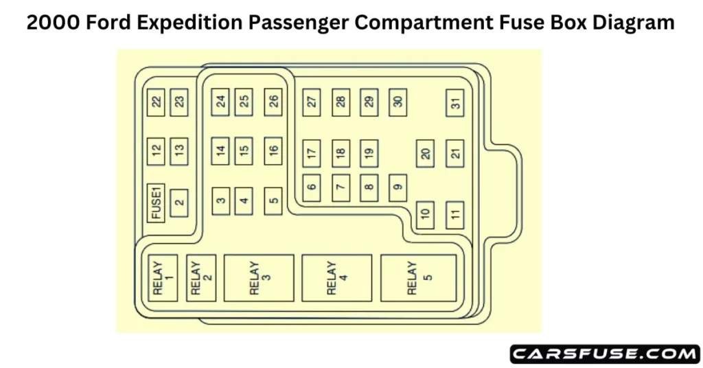
| Fuse/Relay Location | Fuse AmpRating | Passenger Compartment Fuse Panel Description |
| 1 | 15A | Audio |
| 2 | 5A | Powertrain Control Module (PCM), Cluster |
| 3 | 20A | Cigar Lighter, OBD-II Scan Tool Connector |
| 4 | 5A | Remote Entry Module, Mirrors |
| 5 | 15A | Speed Control Module, ReverseLamp, Climate Mode Switch, Daytime Running Lamp Relay |
| 6 | 5A | Cluster, Brake Shift Interlock Solenoid, GEM Module |
| 7 | — | Not Used |
| 8 | 5A | Radio, Remote Entry Module, GEM Module |
| 9 | — | Not Used |
| 10 | — | Not Used |
| 11 | 30A | Front Washer Pump Relay, WiperRun/Park Relay, Wiper Hi/LO Relay, Windshield Wiper Motor |
| 12 | — | Not Used |
| 13 | 20A | Stop Lamp Switch (Lamps), Turn/Hazard Flasher, Speed ControlModule |
| 14 | 15A | Battery Saver Relay, Interior LampRelay, Accessory Delay Relay (PowerWindows) |
| 15 | 5A | Stop Lamp Switch, (Speed Control, Brake Shift Interlock, ABS, PCMModule Inputs), GEM Module, RABSTest Connector |
| 16 | 20A | Headlamps (Hi Beams), Cluster (Hi Beam Indicator) |
| 17 | — | Not Used |
| 18 | 5A | Instrument Illumination (Dimmer Switch Power) |
| 19 | — | Not Used |
| 20 | 5A | Audio, GEM (or CTM) Module, Powertrain Control Module (PCM), |
| 21 | 15A | Starter Relay, Clutch Switch, Fuse 20 |
| 22 | 10A | Air Bag Module, Passenger Airbag Deactivation Module, Climate ModeSwitch (Blower Relay) |
| 23 | 10A | Trailer Tow Battery Charge Relay, Turn/Hazard Flasher, 4×4 Solenoids,4×4 Relays, Overhead Console, 4Wheel Anti-Lock Brake System(4WABS) Module |
| 24 | — | Not Used |
| 25 | — | Not Used |
| 26 | 10A | Right Side Low Beam Headlamp |
| 27 | 5A | Foglamp Relay and FoglampIndicator |
| 28 | 10A | Left Side Low Beam Headlamp |
| 29 | 5A | Autolamp Module, Transmission Overdrive Control Switch |
| 30 | 30A | Passive Anti Theft Transceiver, Cluster, Ignition Coils, PowertrainControl Module Relay |
| 31 | — | Not Used |
| Relay 1 | — | Interior Lamp Relay |
| Relay 2 | — | Battery Saver Relay |
| Relay 3 | — | Not Used |
| Relay 4 | — | One Touch Down Window Relay |
| Relay 5 | — | ACC Delay Relay |
2000 Ford Expedition Standard fuse amperage rating and color
| Fuse Rating | Mini Fuses | Standard Fuses | Maxi Fuses | Cartridge Maxi Fuses | Fuse Link Cartridge |
| 2A | Grey | Grey | — | — | — |
| 3A | Violet | Violet | — | — | — |
| 4A | Pink | Pink | — | — | — |
| 5A | Tan | Tan | — | — | — |
| 7.5A | Brown | Brown | — | — | — |
| 10A | Red | Red | — | — | — |
| 15A | Blue | Blue | — | — | — |
| 20A | Yellow | Yellow | Yellow | Blue | Blue |
| 25A | Natural | Natural | — | — | — |
| 30A | Green | Green | Green | Pink | Pink |
| 40A | — | — | Orange | Green | Green |
| 50A | — | — | Red | Red | Red |
| 60A | — | — | Blue | — | Yellow |
| 70A | — | — | Tan | — | Brown |
| 80A | — | — | Natural | — | Black |
