
In this article, of the 2001 Ford Expedition fuse box diagram we will take a deep dive into this invaluable resource.
With a meticulous breakdown of each fuse’s function, we aim to provide you by explaining the purpose of fuses, their locations, and the corresponding electrical systems which protect seamless operation of your Ford Expedition electrical components.
Table of Contents
Note: All information contained in this Quick Reference Guide was accurate at the time of duplication. For detailed operating and safety information, please consult your Owner’s Manual.
2001 Ford Expedition Fuse Box Diagram Chart (Engine Compartment)
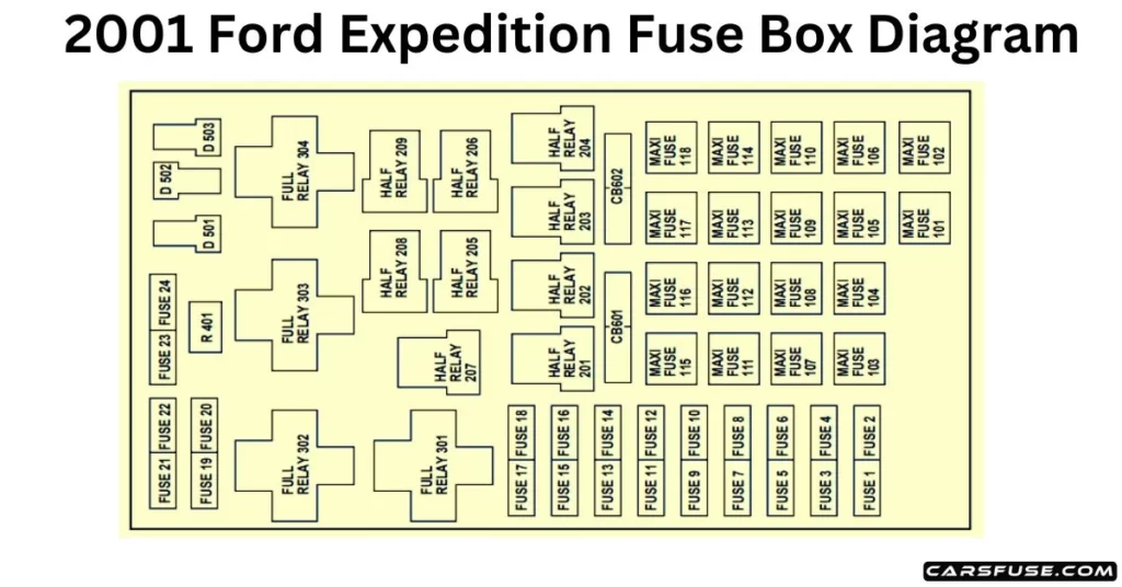
Note: In the event that you need to disconnect and reconnect the battery, it's important to note that certain features may require resetting. This step is necessary to restore their functionality.

*Mini fuses / **Maxi fuses
| Fuse/RelayLocation | Fuse AmpRating | Power Distribution Box Description |
| 1 | 20A * | PowerPoint |
| 2 | 30A* | Powertrain Control Module |
| 3 | 30A* | Headlamps/Autolamps |
| 4 | 20A* | Console Powerpoint |
| 5 | 20A* | Trailer Tow Backup/Park Lamps |
| 6 | 15A* | Parklamps/Autolamps, Feeds PassengerCompartment Fuse 18 |
| 7 | 20A* | Horn |
| 8 | 30A* | Power Door Locks |
| 9 | 15A* | Daytime Running Lamps (DRL), FogLamps |
| 10 | 20A* | Fuel Pump |
| 11 | 20A* | Alternator Field |
| 12 | 10A* | Rear Wipers |
| 13 | 15A* | A/C Clutch |
| 14 | — | Not Used |
| 15 | 10A* | Running Board Lamps |
| 16 | — | Not Used |
| 17 | 10A* | Flip Windows |
| 18 | 15A* | Powertrain Control Module, FuelInjectors, Fuel Pump, Mass Air FlowSensor |
| 19 | 10A* | Trailer Tow Stop and Right Turn Lamp |
| 20 | 10A* | Trailer Tow Stop and Left Turn Lamp |
| 21 | — | Not Used |
| 22 | — | Not Used |
| 23 | 15A* | HEGO Sensors, Canister Vent, Automatic Transmission, CMS Sensor |
| 24 | — | Not Used |
| 101 | 30A** | Trailer Tow Battery Charge |
| 102 | 50A** | Four-Wheel Antilock Brake Module |
| 103 | 50A** | Junction Block Battery Feed |
| 104 | 30A** | 4×4 Shift Motor & Clutch |
| 105 | 40A** | Climate Control Front Blower |
| 106 | — | Not Used |
| 107 | — | Not Used |
| 108 | 30A** | Trailer Tow Electric Brake |
| 109 | 50A** | Air Suspension Compressor |
| 110 | 30A** | Heated Seats |
| 111 | 40A** | Ignition Switch Battery Feed (Run/StartCircuit) |
| 112 | 30A** | Drivers Power Seat, Adjustable Pedals, Memory Module |
| 113 | 40A** | Ignition Switch Battery Feed (Run and Accessory Circuits) |
| 114 | 30A** | Climate Control Auxiliary Blower |
| 115 | — | Not Used |
| 116 | 40A** | Rear Window Defroster, Heated Mirrors |
| 117 | — | Not Used |
| 118 | — | Not Used |
| 201 | — | Trailer Tow Park Lamp Relay |
| 202 | — | Front Wiper Run/Park Relay |
| 203 | — | Trailer Tow Backup Lamp Relay |
| 204 | — | A/C Clutch Relay |
| 205 | — | Rear Wiper Down |
| 206 | — | Foglamp Relay |
| 207 | — | Front Washer Pump Relay |
| 208 | — | Rear Washer Pump Relay |
| 209 | — | Rear Wiper Up |
| 301 | — | Fuel Pump Relay |
| 302 | — | Trailer Tow Battery Charge Relay |
| 303 | — | Wiper Hi/Lo Relay |
| 304 | — | Powertrain Control Module Relay |
| 401 | — | Not Used |
| 501 | — | Powertrain Control Module Diode |
| 502 | — | A/C Clutch Diode |
| 503 | — | Not Used |
| 601 | 30A | Delayed Accessory (Power Windows, Flip Windows, Moonroof) |
| 602 | — | Not Used |
2001 Ford Expedition Fuse Box Diagram Chart (Passenger Compartment)
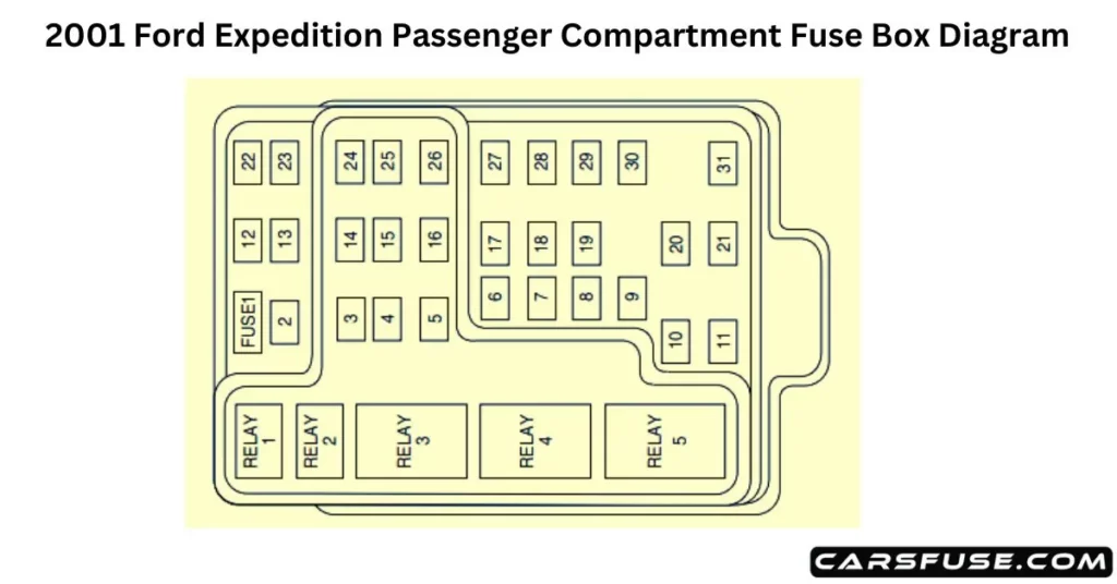
| Fuse/RelayLocation | Fuse AmpRating | Passenger Compartment Fuse Panel Description |
| 1 | 25A | Audio |
| 2 | 5A | Overhead Trip Computer, ElectronicAutomatic Temperature Control (EATC), Powertrain Control Module (PCM), Cluster |
| 3 | 20A | Cigar Lighter, OBD-II Scan ToolConnector |
| 4 | 7.5A | Remote Entry Module, Mirrors, MemoryFunctions (Seats and Pedals) |
| 5 | 15A | Speed Control Module, Reverse Lamp, EVO Module, Climate Mode Switch(Front Blower Relay), Daytime RunningLamp Relay, Reverse Sensing System, Autolock, E/C Mirror |
| 6 | 5A | Cluster, Overhead Trip Computer, Compass, Brake Shift Interlock Solenoid, Air Suspension Module, GEM Module, EVO Steering Sensor, Heated Mirror, RearDefroster, Reverse Sensing System |
| 7 | 5A | Aux A/C Blower Relay (via fuse 22) |
| 8 | 5A | Radio, Remote Entry Module, GEMModule |
| 9 | — | Not Used |
| 10 | — | Not Used |
| 11 | 30A | Front Washer Pump Relay, WiperRun/Park Relay, Wiper Hi/LO Relay, Windshield Wiper Motor, Rear WasherPump Relay |
| 12 | 15A | Air Suspension Switch |
| 13 | 20A | Stop Lamp Switch (Lamps), Turn/HazardFlasher, Speed Control Module |
| 14 | 15A | Rear Wipers, Running Board Lamps, Battery Saver Relay, Interior Lamp Relay, Accessory Delay Relay (Power Windows, Moonroof, Flip Windows) |
| 15 | 5A | Stop Lamp Switch, (Speed Control, BrakeShift Interlock, ABS, PCM Module Inputs, Air Suspension Module, Autolock), GEMModule |
| 16 | 20A | Headlamps (Hi Beams), Cluster (Hi BeamIndicator) |
| 17 | 10A | Heated Mirrors, Heated Grid SwitchIndicator |
| 18 | 5A | Instrument Illumination (Dimmer SwitchPower) |
| 19 | — | Not Used |
| 20 | 5A | Audio, Air Suspension Module, GEMModule, Memory Module |
| 21 | 15A | Starter Relay, Fuse 20, TransmissionRange Switch |
| 22 | 10A | Air Bag Module, Intelligent PassengerAirbag Deactivation Module |
| 23 | 10A | Aux A/C, Heated Seats, Trailer TowBattery Charge, Turn/Hazard Flasher, 4×4Clutch Relay, Overhead Console, E/CMirror, 4 Wheel Anti-Lock Brake System(4WABS) Module |
| 24 | 10A | EATC Module, EATC Blower Relay, Climate Control Switch Assembly, FeedsFuse 7 |
| 25 | — | Not Used |
| 26 | 10A | Right Side Low Beam Headlamp |
| 27 | 5A | Foglamp Relay and Foglamp Indicator |
| 28 | 10A | Left Side Low Beam Headlamp |
| 29 | 5A | Autolamp Module, TransmissionOverdrive Control Switch |
| 30 | 30A | Passive Anti Theft Transceiver, Cluster, Ignition Coils, Powertrain Control ModuleRelay |
| 31 | 10A | Rear Integrated Control Panel (Audio), CD Player |
| Relay 1 | — | Interior Lamp Relay |
| Relay 2 | — | Battery Saver Relay |
| Relay 3 | — | Rear Window Defroster Relay |
| Relay 4 | — | One Touch Down Window Relay |
| Relay 5 | — | ACC Delay Relay |
2001 Ford Expedition Standard fuse amperage rating and color
| Fuse rating | Mini fuses | Standard fuses | Maxi fuses | Cartridge maxi fuses | Fuse link cartridge |
| 2A | Grey | Grey | — | — | — |
| 3A | Violet | Violet | — | — | — |
| 4A | Pink | Pink | — | — | — |
| 5A | Tan | Tan | — | — | — |
| 7.5A | Brown | Brown | — | — | — |
| 10A | Red | Red | — | — | — |
| 15A | Blue | Blue | — | — | — |
| 20A | Yellow | Yellow | Yellow | Blue | Blue |
| 25A | Natural | Natural | — | — | — |
| 30A | Green | Green | Green | Pink | Pink |
| 40A | — | — | Orange | Green | Green |
| 50A | — | — | Red | Red | Red |
| 60A | — | — | Blue | — | Yellow |
| 70A | — | — | Tan | — | Brown |
| 80A | — | — | Natural | — | Black |
