
In this article, we’ll explore the 1999 Ford Expedition fuse box diagram in a way that’s easy to understand. We’ll explain what each fuse does, so you can have a better understanding of how your vehicle’s electrical system works.
By learning about each fuse’s function of your Ford Expedition, you’ll be able to figure out which fuse might be causing a problem if something isn’t working properly. With the fuse box diagram as your guide, you’ll be able to navigate through your car’s electrical system and find the right fuse quickly.
Table of Contents
Note: All information contained in this Quick Reference Guide was accurate at the time of duplication. For detailed operating and safety information, please consult your Owner’s Manual.
1999 Ford Expedition Fuse Box Diagram (Power distribution box)
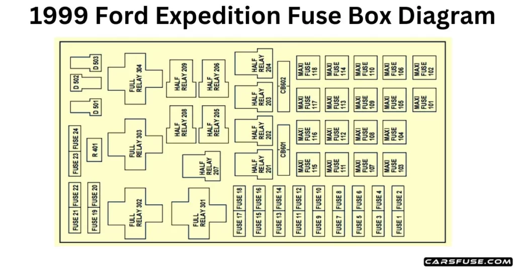
*Mini fuses /**Maxi fuses
| Fuse/RelayLocation | Fuse AmpRating | Description |
| 1 | 25A * | PowerPoint |
| 2 | 30A* | Powertrain Control Module |
| 3 | 30A* | Headlamps/Autolamps |
| 4 | 25A* | Console Powerpoint |
| 5 | 20A* | Trailer Tow Backup/Park Lamps |
| 6 | 15A* | Parklamps/Autolamps |
| 7 | 20A* | Horn |
| 8 | 30A* | Power Door Locks |
| 9 | 15A* | Daytime Running Lamps (DRL), Fog Lamps |
| 10 | 20A* | Fuel Pump |
| 11 | 20A* | Alternator Field |
| 12 | 10A* | Rear Wipers |
| 13 | — | Not Used |
| 14 | — | Not Used |
| 15 | 10A* | Running Board Lamps |
| 16 | — | Not Used |
| 17 | — | Not Used |
| 18 | 15A* | Powertrain Control Module, Fuel Injectors, Fuel Pump, Mass Air Flow Sensor |
| 19 | 10A* | Trailer Tow Stop and Right Turn Lamp |
| 20 | 10A* | Trailer Tow Stop and Left Turn Lamp |
| 21 | — | Not Used |
| 22 | — | Not Used |
| 23 | 15A* | Powertrain Control Module, HEGO Sensors, Canister Vent |
| 24 | 15A* | Powertrain Control Module, AutomaticTransmission, CMS Sensor |
| 101 | 30A** | Trailer Tow Battery Charge |
| 102 | 50A** | Moonroof, Flip Windows, and Heated Seats |
| 103 | 50A** | Junction Block Battery Feed |
| 104 | 30A** | 4×4 Shift Motor & Clutch |
| 105 | 40A** | Climate Control Front Blower |
| 106 | — | Not Used |
| 107 | — | Not Used |
| 108 | 30A** | Trailer Tow Electric Brake |
| 109 | 50A** | Air Suspension Compressor |
| 110 | 30A** | Moonroof, Flip Windows and Heated Seats |
| 111 | 50A** | Ignition Switch Battery Feed (Start Circuit) |
| 112 | 30A** | Drivers Power Seat, Adjustable Pedals |
| 113 | 50A** | Ignition Switch Battery Feed (Run and Accessory Circuits) |
| 114 | 30A** | Climate Control Auxiliary Blower |
| 115 | — | Not Used |
| 116 | 40A** | Rear Window Defroster, Heated Mirrors |
| 117 | — | Not Used |
| 118 | — | Not Used |
| 201 | — | Trailer Tow Park Lamp Relay |
| 202 | — | Front Wiper Run/Park Relay |
| 203 | — | Trailer Tow Backup Lamp Relay |
| 204 | — | A/C Clutch Relay |
| 205 | — | Horn Relay |
| 206 | — | Foglamp Relay |
| 207 | — | Front Washer Pump Relay |
| 208 | — | Rear Washer Pump Relay |
| 209 | — | Front Wiper Hi/Lo Relay |
| 210 | — | Not Used |
| 211 | — | Not Used |
| 212 | — | Rear Wiper Up Relay |
| 213 | — | Rear Wiper Down Relay |
| 301 | — | Fuel Pump Relay |
| 302 | — | Trailer Tow Battery Charge Relay |
| 303 | — | Not Used |
| 304 | — | Powertrain Control Module Relay |
| 401 | — | Not Used |
| 501 | — | Powertrain Control Module Diode |
| 502 | — | A/C Clutch Diode |
| 503 | — | Not Used |
| 601 | 30A | Delayed Accessory (Power Windows, FlipWindows, Moonroof) |
| 602 | — | Not Used |
Important: Always disconnect the battery before servicing high-current fuses. To reduce the risk of electrical shock, always replace the cover with the power distribution box before reconnecting the battery or refilling fluid reservoirs. Always replace a fuse with one that has the specified amperage rating. Using a fuse with a higher amperage rating can cause severe wire damage and could start a fire.
1999 Ford Expedition Fuse Box Diagram (Passenger compartment panel)
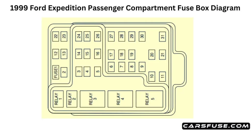
| Fuse/Relay Location | Fuse AmpRating | Description |
| 1 | 25A | Audio |
| 2 | 5A | Overhead Trip Computer, ElectronicAutomatic Temperature Control (EATC), Powertrain Control Module (PCM), Cluster |
| 3 | 20A | Cigar Lighter, OBD-II Scan Tool Connector |
| 4 | 15A | Autolamp Module, Remote Entry Module, Mirrors, Air Suspension Switch |
| 5 | 15A | AC Clutch Relay, Speed Control Module, Reverse Lamp, EVO Module, Climate ModeSwitch (Front Blower Relay), DaytimeRunning Lamp Relay |
| 6 | 5A | Cluster, Overhead Trip Computer, Compass, Brake Shift Interlock Solenoid, AirSuspension Module, GEM Module, EVOSteering Sensor |
| 7 | 5A | Aux A/C Blower Relay, Console Blower |
| 8 | 5A | Radio, Remote Entry Module, GEM Module |
| 9 | — | Not Used |
| 10 | — | Not Used |
| 11 | 30A | Front Washer Pump Relay, Wiper Run/ParkRelay, Wiper Hi/LO Relay, Windshield WiperMotor, Rear Washer Pump Relay |
| 12 | — | Not Used |
| 13 | 20A | Stop Lamp Switch (Lamps), Turn/Hazard Flasher, Speed Control Module |
| 14 | 15A | Rear Wipers, Running Board Lamps, Battery Saver Relay, Interior Lamp Relay, Accessory Delay Relay (Power Windows) |
| 15 | 5A | Stop Lamp Switch, (Speed Control, BrakeShift Interlock, ABS, PCM Module Inputs), GEM Module |
| 16 | 20A | Headlamps (Hi Beams), Cluster (Hi BeamIndicator) |
| 17 | 10A | Heated Mirrors, Heated Grid SwitchIndicator |
| 18 | 5A | Instrument Illumination (Dimmer Switch Power) |
| 19 | — | Not Used |
| 20 | 5A | Audio, Four Wheel Air Suspension (4WAS) Module, GEM Module |
| 21 | 15A | Starter Relay, Fuse 20 |
| 22 | 10A | Air Bag Module |
| 23 | 10A | Aux A/C, Heated Seats, Trailer Tow BatteryCharge, Turn/Hazard Flasher, ConsoleBlower Door Actuator |
| 24 | 10A | Climate Mode Switch (Blower Relay), EATC (via fuse 7), EATC Blower Relay |
| 25 | 5A | 4 Wheel Anti-Lock Brake System (4WABS)Module |
| 26 | 10A | Right Side Low Beam Headlamp |
| 27 | 5A | Foglamp Relay and Foglamp Indicator |
| 28 | 10A | Left Side Low Beam Headlamp |
| 29 | 5A | Autolamp Module, Transmission Overdrive Control Switch |
| 30 | 30A | Passive Anti Theft Transceiver, Cluster, Ignition Coils, Powertrain Control Module Relay |
| 31 | 10A | Rear Integrated Control Panel (Audio), CD Player |
| Relay 1 | — | Interior Lamp Relay |
| Relay 2 | — | Battery Saver Relay |
| Relay 3 | — | Rear Window Defroster Relay |
| Relay 4 | — | One Touch Down Window Relay |
| Relay 5 | — | ACC Delay Relay |
1999 Ford Expedition Standard fuse amperage rating and color
| Fuse Rating | Mini Fuses | Standard Fuses | Maxi Fuses | Cartridge Maxi Fuses | Fuse Link Cartridge |
| 2A | Grey | Grey | — | — | — |
| 3A | Violet | Violet | — | — | — |
| 4A | Pink | Pink | — | — | — |
| 5A | Tan | Tan | — | — | — |
| 7.5A | Brown | Brown | — | — | — |
| 10A | Red | Red | — | — | — |
| 15A | Blue | Blue | — | — | — |
| 20A | Yellow | Yellow | Yellow | Blue | Blue |
| 25A | Natural | Natural | — | — | — |
| 30A | Green | Green | Green | Pink | Pink |
| 40A | — | — | Orange | Green | Green |
| 50A | — | — | Red | Red | Red |
| 60A | — | — | Blue | — | Yellow |
| 70A | — | — | Tan | — | Brown |
| 80A | — | — | Natural | — | Black |
