
A detailed Guide to the 1998 Ford Expedition Fuse Box Diagram, Step-by-step, we walk you through the 1998 Ford Expedition’s Electrical System, providing clear charts and annotations to help you become a master of your truck’s electrical system.
Whether you’re a visual learner or simply prefer a hands-on approach, this article will serve as your go-to resource for understanding electrical issues.
Table of Contents
Note: All information contained in this Quick Reference Guide was accurate at the time of duplication. For detailed operating and safety information, please consult your Owner’s Manual.
1998 Ford Expedition Fuse Box Diagram Chart (Power Distribution Box)
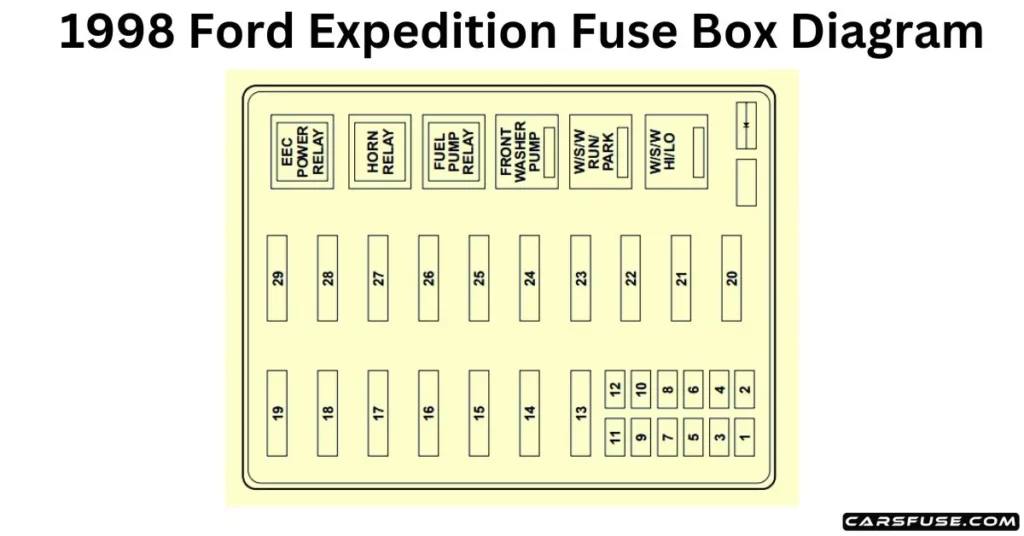
Note: In the event that you need to disconnect and reconnect the battery, it's important to note that certain features may require resetting. This step is necessary to restore their functionality.

* Mini Fuses / ** Maxi Fuses
| Fuse/RelayLocation | Fuse AmpRating | Description |
| 1 | 20A* | Trailer Tow Running Lamp Relay, Trailer Tow Backup Lamp Relay |
| 2 | 10A* | Air Bag Diagnostic Monitor |
| 3 | 30A* | All Unlock Relay, All Lock Relay, Driver’s Unlock Relay |
| 4 | 15A* | Air Suspension Service Switch |
| 5 | 20A* | Horn Relay |
| 6 | 30A* | Radio, Premium Sound Amplifier, CD Changer, Rear IntegratedControl Panel, Sub-Woofer Power(Fuse 3 & Fuse 5) |
| 7 | 15A* | Main Light Switch, Park LampRelay |
| 8 | 30A* | Main Light Switch, HeadlampRelay, Multi-Function Switch |
| 9 | 15A* | Daytime Running Lamps (DRL)Module, Fog Lamp Relay |
| 10 | 25A* | I/P Auxiliary Power Socket |
| 11 | 25A* | Console Auxiliary Power Socket |
| 12 | 10A* | Rear Wiper Up Motor Relay, RearWiper Down Motor Relay |
| 13 | 30A** | Auxiliary A/C Relay |
| 14 | 60A** | 4 Wheel Anti-Lock Brake System(4WABS) Module |
| 15 | 50A** | Air Suspension Solid StateCompressor Relay |
| 16 | 40A** | Trailer Tow Battery Charge Relay, Engine Fuse Module (Fuse 2) |
| 17 | 30A** | Shift on the Fly Relay, TransferCase Shift relay |
| 18 | 30A** | Power Seat Control Switch |
| 19 | 20A** | Fuel Pump Relay |
| 20 | 50A** | Ignition Switch (B4 & B5) |
| 21 | 50A** | Ignition Switch (B1 & B3) |
| 22 | 50A** | Junction Box Fuse/Relay PanelBattery Feed |
| 23 | 40A** | I/P Blower Relay |
| 24 | 30A** | PCM Power Relay, Engine FuseModule (Fuse 1) |
| 25 | 30A CB | Junction Box Fuse/Relay Panel, ACC Delay Relay |
| 26 | — | Not Used |
| 27 | 40A** | Junction Box Fuse/Relay Panel, Heated Grid Relay |
| 28 | 30A** | Trailer Electronic BrakeController |
| 29 | 30A** | Flip Window Relay, HybridCooling Fan Relay |
1998 Ford Expedition Fuse Box Diagram (Passenger compartment panel)
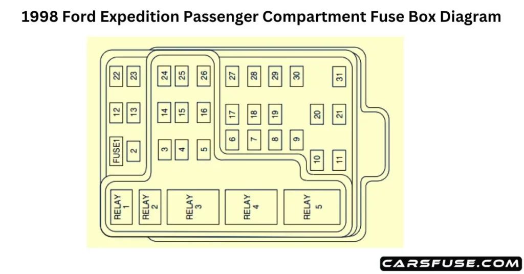
| Fuse/RelayLocation | Fuse AmpRating | Description |
| 1 | 15A | Flasher Relay |
| 2 | 5A | Instrument Cluster, Overhead TripComputer (OTC) Module |
| 3 | 25A | Cigar Lighter |
| 4 | 5A | Park Lamp Relay, HeadlampRelay, Autolamp Module, RemoteAnti-Theft Personality (RAP)Module, Power Mirror Switch |
| 5 | 15A | Digital Transmission Range (DTR)Sensor, Daytime Running Lamps(DRL) Module, Speed ControlServo/Amplifier Assembly, Heater-A/C Control Assembly, Blend Door Actuator, ElectronicVariable Orifice (EVO) Module |
| 6 | 5A | Shift Lock Actuator, GenericElectronic Module (GEM), 4Wheel Air Suspension (4WAS)Module, Compass Sensor, SteeringWheel Rotation Sensor, HeatedGrid Relay, Overhead TripComputer (OTC) Module |
| 7 | 5A | Auxiliary A/C Relay, ConsoleBlower Motor |
| 8 | 5A | Radio, Main Light Switch, RemoteAnti-Theft Personality (RAP)Module |
| 9 | — | Not Used |
| 10 | — | Not Used |
| 11 | 30A | Washer Pump Relay, WiperRun/Park Relay, Wiper Hi/LoRelay, Windshield Wiper Motor, Rear Wiper Pump Relay |
| 12 | 5A | Data Link Connector (DLC) |
| 13 | 15A | Brake On/Off (BOO) Switch, Brake Pressure Switch |
| 14 | 15A | Battery Saver Relay, InteriorLamp Relay |
| 15 | 5A | Generic Electronic Module(GEM), Passive Anti-Theft System(PATS) Module |
| 16 | 20A | Instrument Cluster (W/O DRL), Daytime Running Lamps (DRL)Module, Hi-Beam Headlamps(Power supplied through Multi-Function Switch) |
| 17 | 10A | Heated Backlight Switch, LeftPower/Heated Signal Mirror, RightPower/Heated Signal Mirror |
| 18 | 5A | Main Light Switch, GenericElectronic Module (GEM), Instrument Illumination (Power supplied through Main LightSwitch) |
| 19 | 10A | Instrument Cluster, Air BagDiagnostic Monitor |
| 20 | 5A | 4 Wheel Air Suspension (4WAS), Generic Electronic Module (GEM) |
| 21 | 15A | Digital Transmission Range (DTR)Sensor, Junction Box Fuse/RelayPanel (Fuse 20) |
| 22 | 10A | Air Bag Diagnostic Monitor |
| 23 | 10A | Trailer Tow Battery Charge Relay, 4X4 Center Axle Disconnect solenoid, 4X2 Center Axle Disconnect Solenoid, FunctionSelector Switch, Rear IntegratedControl Panel, RecirculationVacuum Solenoid, Auxiliary A/CMode Acturator, Auxiliary A/C Control Module |
| 24 | 10A | Function Selector Switch |
| 25 | 5A | 4 Wheel Anti-Lock Brake System(4WABS) Module, 4WABS Relay |
| 26 | 10A | Daytime Running Lamps (DRL) Module, Right Headlamp (Power supplied through Multi-FunctionSwitch) |
| 27 | 5A | Main Light Switch, Fog LampRelay |
| 28 | 10A | Left Headlamp |
| 29 | 5A | Autolamp Module, InstrumentCluster, Transmission ControlSwitch (TCS) |
| 30 | 30A | Radio Noise Capacitor, IgnitionCoil, PCM Power Diode, Coil OnPlugs |
| 31 | — | Not Used |
1998 Ford Expedition Standard fuse amperage rating and color
| Fuse rating | Color |
| 5 amp | Tan |
| 7.5 amp | Brown |
| 10 amp | Red |
| 15 amp | Light blue |
| 20 amp | Yellow |
| 20 amp fuse link | Light blue |
| 25 amp | Natural |
| 30 amp | Light green |
| 30 amp fuse link | Pink |
| 40 amp fuse link | Green |
| 50 amp fuse link | Red |
| 60 amp fuse link | Yellow |
| 80 amp fuse link | Black |
| 100 amp fuse link | Dark blue |
1998 Ford Expedition Primary battery fuses (Mega fuses)
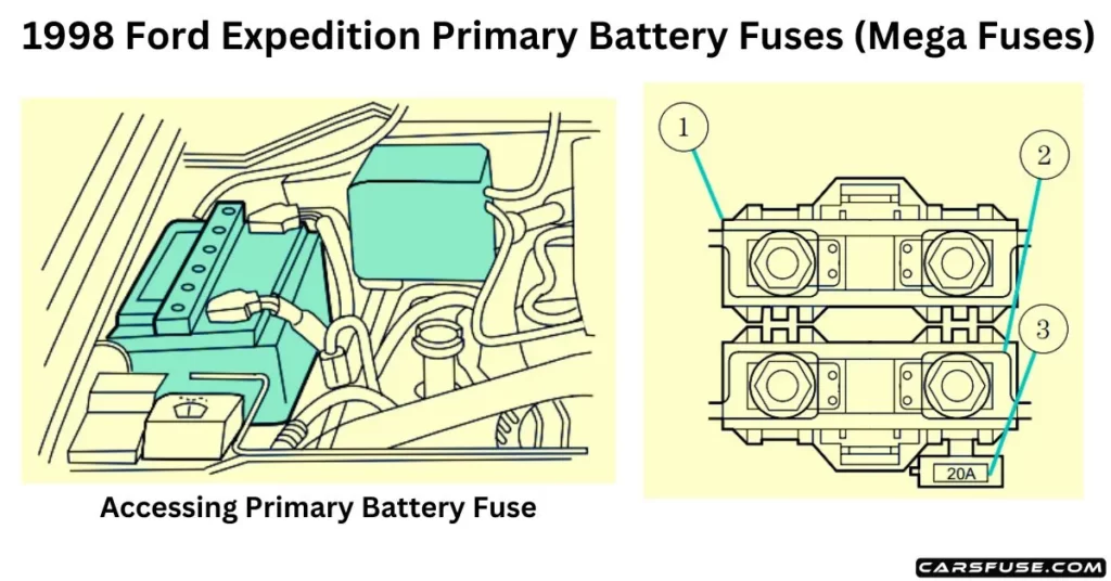
| Location | Amperage | Description |
| 1 | 175 | Power Network Box Megafuse |
| 2 | 175 | Alternator Megafuse |
| 3 | 20 | Alternator Field Minifuse |
1998 Ford Expedition Engine mini fuse box
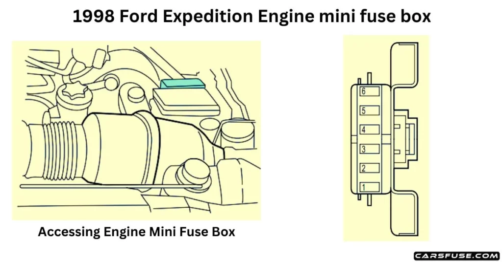
| SlotNumber | FuseAmperageRating | Circuits Protected |
| 1 | 5 amp | Powertrain Control Module (PCM) |
| 2 | 20 amp | Trailer Tow Stop/Turn Lamps |
| 3 | 10 amp | Audio Rear Integrated Control Panel(RICP), Compact Disc Changer, Radio |
| 4 | 10 amp | Running Board Lamps |
| 5 | 20 amp | Amplifier, Subwoofer Amplifier |
| 6 | — | Not Used |
