
In this article, we will provide you with an in-depth exploration of the 1997 Ford Expedition fuse box diagram. We’ll unravel the complexities and demystify the purpose of each fuse, enabling you to navigate your electrical system with confidence and ease.
Table of Contents
Note: All information contained in this Quick Reference Guide was accurate at the time of duplication. For detailed operating and safety information, please consult your Owner’s Manual.
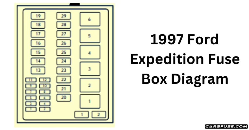
1997 Ford Expedition Fuse Box Diagram Chart (Power Network Box)
Note: In the event that you need to disconnect and reconnect the battery, it's important to note that certain features may require resetting. This step is necessary to restore their functionality.
| Slot number | Fuse amperage rating | Circuits protected |
| 1 | 20 amp | Trailer tow backup & tail lamps |
| 2 | 10 amp | Airbag diagnostic monitor |
| 3 | 30 amp | Power locks |
| 4 | 15 amp | Air suspension |
| 5 | 20 amp | Horn |
| 6 | 30 amp | Engine mini fuse box fuses #3 and #5 |
| 7 | 15 amp | Park and tail lamps |
| 8 | 30 amp | Headlamps |
| 9 | 15 amp | Fog lamps and DRL |
| 10 | 25 amp | Auxiliary instrument panel (I/P) powerpoint |
| 11 | 25 amp | Auxiliary console powerpoint |
| 12 | 10 amp | Rear wiper |
| 13 | 30 amp | Auxiliary blower |
| 14 | 60 amp | Four-wheel anti-lock brake system (4WABS) |
| 15 | 50 amp | Air suspension compressor |
| 16 | 40 amp | Trailer tow battery charge, engine mini fuse box fuse #2, engine mini fuse box fuse #4 |
| 17 | 30 amp | Four-wheel drive (4WD) transfer case motor and clutch |
| 18 | 30 amp | Driver power seat |
| 19 | 20 amp | Fuel pump |
| 20 | 50 amp | Junction box ignition switched feed |
| 21 | 50 amp | Junction box ignition switched feed |
| 22 | 50 amp | Junction box battery feed |
| 23 | 40 amp | Front blower |
| 24 | 30 amp | Powertrain control module power |
| 25 | 30 C.B. | Windows |
| 26 | – | not used |
| 27 | 40 amp | Heated backlite and mirrors |
| 28 | 30 amp | Trailer tow electric brake |
| 29 | 30 amp | Hybrid fan, moon roof, flip windows |
| Slot number | Fuse amperage rating | Description |
| 1 | – | not used |
| 2 | – | PCM diode |
| Slot number | Fuse amperage rating | Description |
| 1 | – | Windshield wipers high/low speed |
| 2 | – | Windshield wipers run/park |
| 3 | – | Front washer pump relay |
| 4 | – | Fuel pump relay |
| 5 | – | Horn relay |
| 6 | – | PCM power relay |
Important: Always disconnect the battery before servicing high-current fuses. To reduce the risk of electrical shock, always replace the cover with the power distribution box before reconnecting the battery or refilling fluid reservoirs. Always replace a fuse with one that has the specified amperage rating. Using a fuse with a higher amperage rating can cause severe wire damage and could start a fire.
1997 Ford Expedition Engine Mini Fuse Box
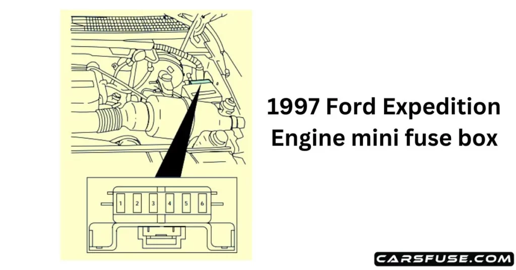
| Slot number | Fuse amperage rating | Circuits protected |
| 1 | 5 amp | Powertrain control module (PCM) |
| 2 | 20 amp | Trailer tow stop/turn lamps |
| 3 | 10 amp | Audio rear integrated control panel (RICP), compact disc changer, radio |
| 4 | 10 amp | Running board lamps |
| 5 | 20 amp | Amplifier, subwoofer amplifier |
| 6 | – | Not used |
1997 Ford Expedition Primary Battery Fuses
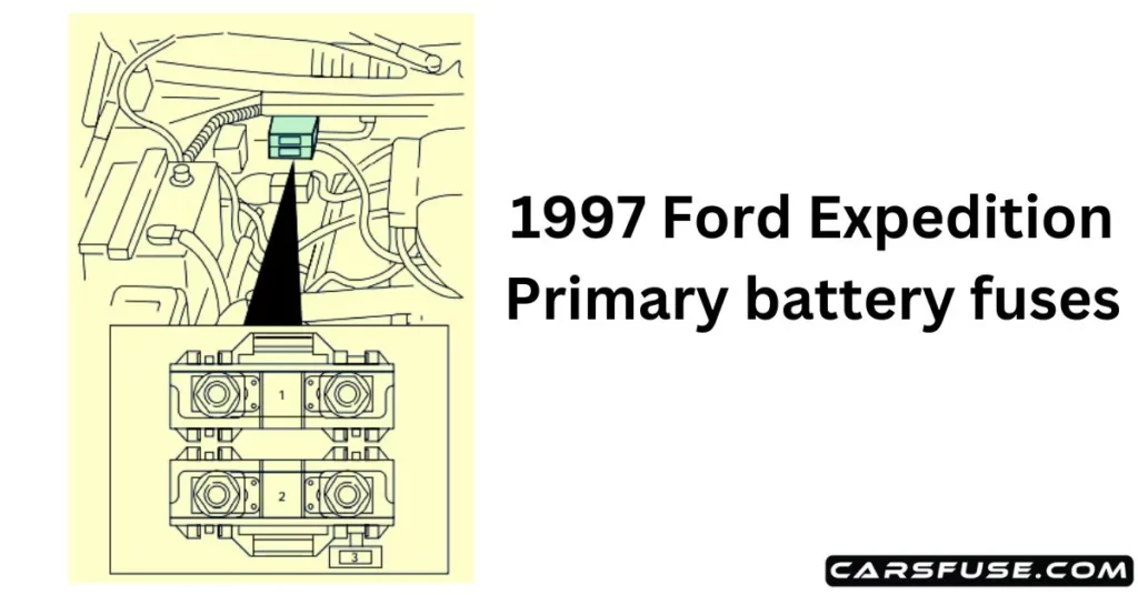
| Location | Amperage | Description |
| 1 | 175 | Power network box mega fuse |
| 2 | 175 | Alternator mega fuse |
| 3 | 20 | Alternator field mini fuse |
1997 Ford Expedition Fuse Box Diagram (Junction Box)
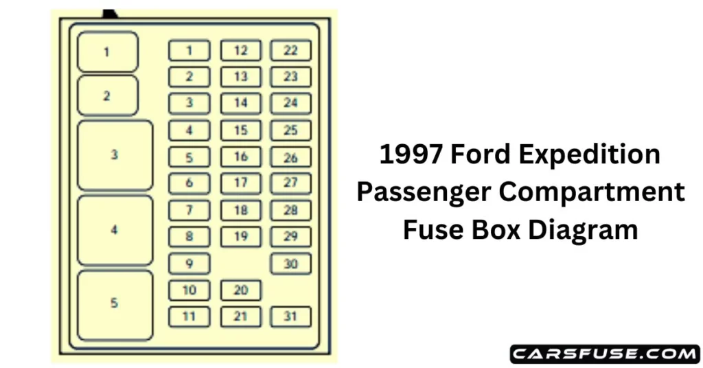
| Slot number | Amperage | Description |
| 1 | 15 amp | Stop/turn lamps |
| 2 | 5 amp | Instrument cluster, trip computer |
| 3 | 25 amp | Cigar lighter |
| 4 | 5 amp | Autolamp module, headlamp relay, remote entry anti-theft with personality module (RAP), power mirrors |
| 5 | 15 amp | Air condition (A/C) clutch, hybrid fan relay, backup lamps, speed control, DRL, instrument panel blend door actuator, electronic variable orifice(EVO) steering module |
| 6 | 5 amp | Generic electronic module(GEM), shift interlock, air suspension module, heated backlite (HBL)relay, steering sensor, trip computer, compass |
| 7 | 5 amp | Console blower, auxiliary blower relay coil |
| 8 | 5 amp | GEM, radio, RAP module |
| 9 | – | Not used |
| 10 | – | Not used |
| 11 | 30 amp | Front wiper motor, washer motor |
| 12 | 5 amp | OBDII scan tool connector |
| 13 | 15 amp | Brake on/off switch, brake pressure switch |
| 14 | 15 amp | Interior lamps, delayed accessory relay, rear wiper relays |
| 15 | 5 amp | GEM, passive anti-theft system (PATS) module |
| 16 | 20 amp | High beam headlamps, high beam indicator |
| 17 | 10 amp | Heated mirrors, heated mirror switch |
| 18 | 5 amp | Instrument and switch illumination |
| 19 | 10 amp | Airbag diagnostic monitor, instrument cluster |
| 20 | 5 amp | GEM, air suspension module |
| 21 | 15 amp | Starter relay, junction box fuse #20 |
| 22 | 10 amp | Airbag diagnostic monitor |
| 23 | 10 amp | Electronic flasher, 4WD vacuum solenoids, trailer tow battery charge relay, console climate door actuator, auxiliary blend, and mode door actuators, auxiliary pot switching module |
| 24 | 10 amp | I/P blower relay, junction fuse box #7 |
| 25 | 5 amp | 4WABS module, 4WABS red lamps relay |
| 26 | 10 amp | Right low beam headlamp, DRL module |
| 27 | 5 amp | Foglamp relay, main lamp switch |
| 28 | 10 amp | Left low beam headlamp |
| 29 | 5 amp | Auto lamp module, instrument cluster, transmission control indicator light, and switch |
| 30 | 30 amp | Ignition coils, PCM relay, PATS module, radio capacitors |
| 31 | – | Not used |
| Slot number | Amperage | Description |
| 1 | – | Interior lamp relay |
| 2 | – | Battery saver relay |
| 3 | – | HBL relay |
| 4 | – | One touch-down relay |
| 5 | – | Accessory delay relay |
1997 Ford Expedition Fuse Ratings
| Fuse rating | Color |
| 5 amp | Beige |
| 10 amp | Red |
| 15 amp | Blue |
| 20 amp | Yellow |
| 25 amp | Natural |
| 30 amp | Green |
| 40 amp | Orange |
| 50 amp | Red |
| 60 amp | Blue |
Enhance your understanding of car electrical systems and address fuse-related challenges with confidence. Please click on the link Can I replace a car fuse by myself? for more information.
