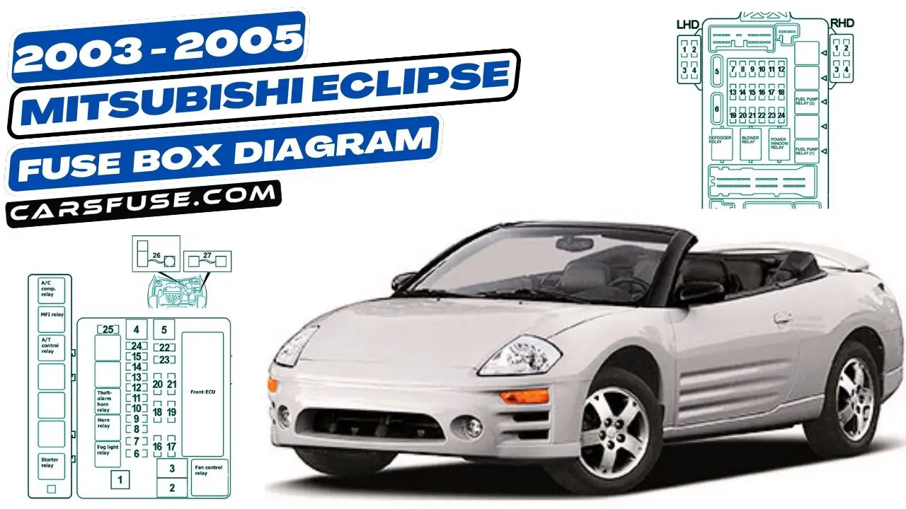
Your Mitsubishi Eclipse is equipped with several fuse boxes that protect the electrical components of your vehicle. If one of these fuses blows, it will prevent power from reaching the affected component. This can cause a variety of problems, such as a malfunctioning radio, dim headlights, or inoperative power windows.
The fuse box diagrams in this blog post will show you the location of all of the fuses in your 2003-2005 Mitsubishi Eclipse, as well as the amperage rating of each fuse. This information can be helpful if you need to replace a fuse in your Eclipse.
Table of Contents
Fuse Box Locations
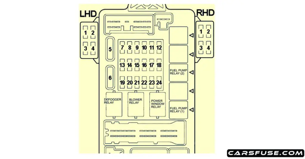
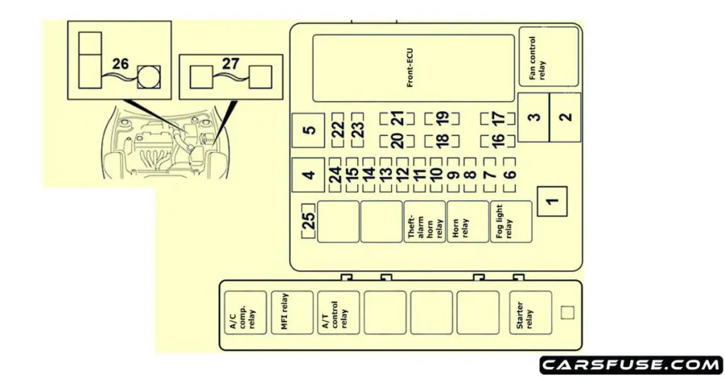
The fuse boxes in your Eclipse are located in the following two locations:
- Under the dashboard on the driver’s side: This fuse box is labeled “Fuse/Relay Box.”
- In the engine compartment: This fuse box is located on the passenger side of the engine compartment, near the firewall.
Passenger Compartment

| Fuse Number | Fuse Amp. Rating | Protected Components |
|---|---|---|
| 1 | 20A | Amplifier |
| 2 | – | – |
| 3 | 20A | Sunroof motor assembly |
| 4 | – | – |
| 5 | 30A | Capacitor, choke coil and defogger |
| 6 | 30A | Automatic compressor controller, blower motor and resistor |
| 7 | – | – |
| 8 | – | – |
| 9 | – | – |
| 10 | 15A | Combination meter, data link connector and ETACS-ECU |
| 11 | 15A | Capacitor, ETACS-ECU and rear wiper motor |
| 12 | – | – |
| 13 | 7.5A | ABS-ECU, convertible top control module and sunroof motor assembly |
| 14 | 7.5A | Remote controlled mirror |
| 15 | – | – |
| 16 | 15A | Accessory socket, cigarette lighter and multi center display unit |
| 17 | 7.5A | Engine control module, fuel pump relay and powertrain control module |
| 18 | 20A | Front-ECU and windshield wiper motor |
| 19 | – | – |
| 20 | 7.5A | A/C compressor relay, A/C switch, automatic compressor controller, blower relay, defogger relay, front-ECU, outside/inside air selection damper control motor, water shut motor and water shut valve controller |
| 21 | 7.5A | Auto-cruise control-ECU and autocruise control switch |
| 22 | 7.5A | Backup light, combination meter, ETACS-ECU, input shaft speed sensor, output shaft speed sensor, powertrain control module and SRS-ECU |
| 23 | 7.5A | Column switch, combination meter, ETACS-ECU, motor antenna assembly, multi center display unit, SRS-ECU and vehicle speed sensor |
| 24 | 10A | Capacitor, distributor assembly and ignition coil |
Engine Compartment

| Fuse Numer | Fuse Amp. Rating | Protected Components |
|---|---|---|
| 1 | 60A | Fuses №5, 6, 10 (in junction block) circuit |
| 2 | 50A | Fan controller |
| 3 | 60A | ABS-ECU |
| 4 | 40A | Ignition switch circuit, theft-alarm horn and theft-alarm horn relay |
| 5 | 30A | Fuses №1, 3 (injunction block) circuit, convertible top control module, power seat assembly, power window main switch and power window motor |
| 6 | 15A | Combination meter and fog light |
| 7 | – | – |
| 8 | 15A | Horn and horn relay |
| 9 | 20A | Camshaft position sensor, crankshaft position sensor, distributor assembly, EGR solenoid valve, engine control module, evaporative emission purge solenoid, evaporative emission ventilation solenoid, heated oxygen sensor, idle air control motor, immobilizer-ECU, injector, MFI relay, powertrain control module, variable induction control solenoid valve and volume air flow sensor |
| 10 | 10A | A/C compressor assembly and automatic compressor controller |
| 11 | 15A | ABS-ECU, auto-cruise control-ECU, capacitor, high-mounted stoplight, immobilizer-ECU, powertrain control module and rear combination light |
| 12 | – | – |
| 13 | 7.5A | Generator |
| 14 | 10A | ETACS-ECU |
| 15 | 20A | A/T control solenoid valve assembly and powertrain control module |
| 16 | 10A | Headlight (RH) |
| 17 | 10A | Headlight (LH) |
| 18 | 10A | Headlight (RH) |
| 19 | 10A | Headlight (LH) |
| 20 | 7.5A | A/C switch, A/T selector lever position illumination light, ashtray illumination light, automatic compressor controller, combination meter, fog light switch, front combination light (RH), glove box light, hazard warning light switch, heater control panel illumination light, multi center display unit, radio, tape player, CD player, rear combination light (RH), rear side marker light (RH) and rheostat |
| 21 | 7.5A | Front combination light (LH), license plate light, rear combination light (LH) and rear side marker light (LH) |
| 22 | 10A | Column switch, combination meter, ETACS-ECU, front-ECU, motor antenna assembly, multi center display unit, radio, tape player, CD player, sunroof motor assembly and vanity mirror light |
| 23 | 10A | ETACS-ECU, motor antenna assembly, radio, tape player and CD player |
| 24 | 15A | Fuel pump module |
| 25 | – | – |
| 26 | 120A | Generator (The fusible link is connected to battery positive terminal) |
| 27 | 30A | Convertible top control module (The fusible link is connected in front of the relay box) |
Next Post: 2001-2005 MG ZR Fuse Box Diagram
Tom Smith is a passionate car mechanic and automotive enthusiast, specializing in the intricate world of car fuse boxes. With years of hands-on experience under the hood, he has earned a reputation as a reliable expert in his field. As the founder and content creator of the popular blog website 'carsfuse.com,' Tom has dedicated himself to sharing his extensive knowledge of car fuse boxes and electrical systems with the world.

