
In this article, we will find out the intricacies of the 2020 Ford Explorer fuse box diagram, and get to the bottom of the mystery behind the fuses & relays that control the vehicle’s electrical operations. A robust electrical system powers various components and functions. These fuses are designed to prevent damage to sensitive components, such as the engine control module, lights, audio system, and other vital circuits from overloads.
Table of Contents
Note: All information contained in this Quick Reference Guide was accurate at the time of duplication. For detailed operating and safety information, please consult your Owner’s Manual.
2020 Ford Explorer Fuse Box Diagram (Engine Compartment)
Note: In the event that you need to disconnect and reconnect the battery, it's important to note that certain features may require resetting. This step is necessary to restore their functionality.
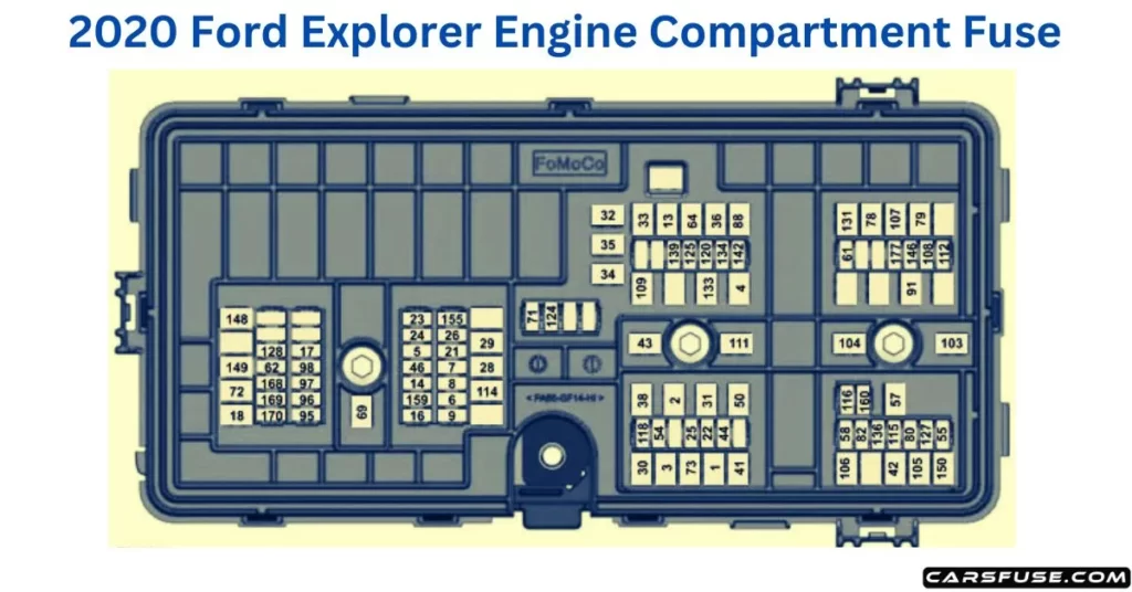
| Fuse or Relay Number | Fuse Rating | Protected Component |
| 1 | 40A | Body control module – battery power in feed 1. |
| 2 | 20A | Power outlet main console bin. |
| 3 | 40A | Body control module – battery power in feed 2. |
| 4 | 30A | Fuel pump. |
| 5 | 5A | Powertrain control module keep alive power. |
| 6 | 20A | Powertrain control module power. |
| 7 | 20A | Canister vent solenoid. Evaporative leak control module. Exhaust gas heat recovery (hybrid electric vehicle). Tank pressure control valve (hybrid electric vehicle). Refueling valve (plug-in hybrid electric vehicle). Vapor blocking valve. Universal exhaust gas oxygen 11. Universal exhaust gas oxygen 21. Catalyst monitor sensor 12. Catalyst monitor sensor 22. Canister purge valve. |
| 8 | 20A | Cooling fan relay coil. Battery interrupt box. Transmission oil pump. Auxiliary coolant pump. Fuel flap door (hybrid electric vehicle). Engine coolant bypass valve. Active grille shutters. |
| 9 | 20A | Ignition coils. |
| 13 | 40A | Front blower motor relay. |
| 14 | 15A | Transmission oil pump. A/C compressor variable clutch. Auxiliary pumps (hybrid electric vehicle). |
| 16 | 15A | Windshield and rear window washer pump relay power. |
| 17 | 5A | Charge status indicator (hybrid electric vehicle). |
| 18 | 30A | Starter motor. |
| 21 | 10A | Headlamp leveling motors. Adaptive headlamps. |
| 22 | 10A | Electric power assisted steering module. |
| 23 | 10A | Anti-lock brake system module with integrated park brake. |
| 24 | 10A | Powertrain control module. Hybrid powertrain control module. |
| 25 | 10A | Air quality sensor. 360 camera with park aid. Rear view camera. Blind spot information system. Adaptive cruise control module. |
| 26 | 15A | Transmission control module. |
| 28 | 40A | Anti-lock brake system valves with integrated park brake. |
| 29 | 60A | Anti-lock brake system pump with integrated park brake. |
| 30 | 30A | Driver seat module. |
| 31 | 30A | Passenger seat motor. |
| 32 | 20A | Front media bin power point. |
| 33 | 20A | Rear cargo area power point. |
| 34 | 20A | Console end cap power point. |
| 35 | 20A | Power point 4. |
| 36 | 40A | Power inverter. |
| 38 | 30A | Climate controlled seat module. |
| 41 | 30A | Power liftgate module. |
| 42 | 30A | Trailer brake control module. |
| 43 | 60A | Body control module. |
| 44 | 10A | Brake on and off switch. |
| 46 | 15A | Battery charger control module (hybrid electric vehicle). |
| 50 | 40A | Heated backlite. |
| 54 | 20A | Heated steering wheel. |
| 55 | 20A | Trailer tow park lamps. |
| 57 | 30A | Trailer tow battery charge. |
| 58 | 10A | Trailer tow backup lamps. |
| 61 | 15A | Multi-contour seat module. |
| 62 | 15A | Headlamp washer pump. |
| 64 | 40A | Four-wheel drive module. |
| 69 | 30A | Front window wiper motor. |
| 71 | 15A | Rear window wiper motor. |
| 72 | 20A | Not used (spare). |
| 73 | 30A | Driver door module. |
| 78 | 50A | Left-hand heated windshield. |
| 79 | 50A | Right-hand heated windshield. |
| 80 | 20A | Trailer tow. |
| 82 | 20A | Not used (spare). |
| 88 | 20A | Rear blower motor. |
| 91 | 20A | Trailer tow lighting module. |
| 95 | 15A | Integrated spark control (hybrid electric vehicle). |
| 96 | 15A | Not used (spare). |
| 97 | 10A | Electric AC (hybrid electric vehicle). High voltage positive temperature coefficient heater (hybrid electric vehicle). |
| 98 | 10A | Traction battery coolant proportional valve (hybrid electric vehicle). |
| 103 | 50A | Not used (spare). |
| 104 | 50A | Not used (spare). |
| 105 | 40A | Not used (spare). |
| 106 | 40A | Not used (spare). |
| 107 | 40A | Not used (spare). |
| 108 | 20A | Not used (spare). |
| 109 | 30A | Passenger door module. |
| 111 | 30A | Body control module voltage quality monitor feed. |
| 112 | 20A | Not used (spare). |
| 114 | 50A | Not used (spare). |
| 115 | 20A | Amplifier. |
| 116 | 5A | Not used (spare). |
| 118 | 30A | Second row heated seats. |
| 120 | 15A | Port fuel injectors. |
| 124 | 5A | Rain sensor. |
| 125 | 5A | USB smart charger 1. |
| 127 | 20A | Amplifier. |
| 128 | 15A | Not used (spare). |
| 131 | 40A | Power folding seat module. |
| 133 | 15A | Heated wiper park. |
| 134 | 10A | Family entertainment system. |
| 136 | 20A | Not used (spare). |
| 139 | 5A | USB smart charger 2. |
| 142 | 5A | Traffic cam. |
| 146 | 15A | Battery electronic control module. |
| 148 | 30A | Left-hand headlamp module. |
| 149 | 30A | Right-hand headlamp module. |
| 150 | 40A | Not used (spare). |
| 155 | 25A | Transmission control module (hybrid electric vehicle). |
| 159 | 15A | DC/DC converter (hybrid electric vehicle). |
| 160 | 10A | Not used (spare). |
| 168 | 20A | Low voltage service disconnect. |
| 169 | 10A | Coolant pump (hybrid electric vehicle). |
| 170 | 10A | Traction battery coolant pump (hybrid electric vehicle). Pedestrian sounder (hybrid electric vehicle). |
| 177 | 10A | Not used (spare). |
2020 Ford Explorer Fuse Box Diagram (Passenger Compartment Fuse Panel)
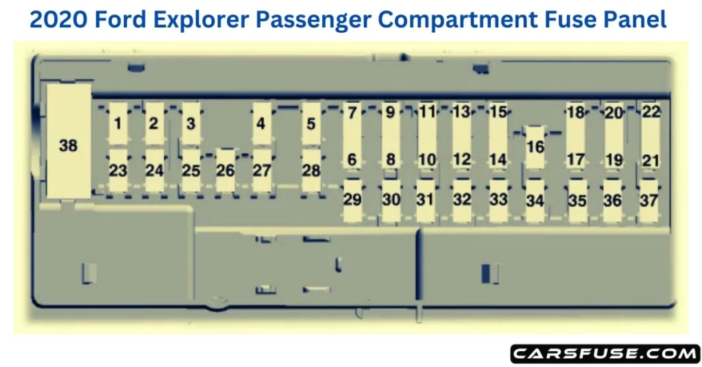
| Fuse or Relay Number | Fuse Rating | Protected Component |
| 1 | — | Not used. |
| 2 | 10A | Moonroof. ERA-GLONAS. eCall. Telematics control unit module. Inverter. Driver door switch pack. |
| 3 | 7.5A | Memory seat switch. Wireless accessory charger module. Seat switches. |
| 4 | 20A | Not used (spare). |
| 5 | — | Not used. |
| 6 | 10A | Not used. |
| 7 | 10A | Smart data link connector power. |
| 8 | 5A | Telematics control unit modem. Hands-free liftgate actuation module. Power liftgate module. |
| 9 | 5A | Keypad switch. Rear climate control. |
| 10 | — | Not used. |
| 11 | — | Not used. |
| 12 | 7.5A | Climate control head. Gear shift module. |
| 13 | 7.5A | Steering column control module. Smart datalink connector. Instrument cluster. |
| 14 | 15A | Not used (spare). |
| 15 | 15A | SYNC. Integrated control panel. |
| 16 | — | Not used. |
| 17 | 7.5A | Headlamp control module. |
| 18 | 7.5A | Not used (spare). |
| 19 | 5A | Headlamp switch. Push button ignition switch. |
| 20 | 5A | Ignition switch. Telematics control unit module. Key inhibit solenoid lock. |
| 21 | 5A | Not used. |
| 22 | 5A | Not used (spare). |
| 23 | 30A | Not used (spare). |
| 24 | 30A | Moonroof. |
| 25 | 20A | Not used (spare). |
| 26 | 30A | Not used (spare). |
| 27 | 30A | Not used (spare). |
| 28 | 30A | Not used (spare). |
| 29 | 15A | Not used (spare). |
| 30 | 5A | Trailer brake connector. |
| 31 | 10A | Terrain management switch. Selectable drive mode switch. Transceiver module. |
| 32 | 20A | Audio control module. |
| 33 | — | Not used. |
| 34 | 30A | Run/start relay. |
| 35 | 5A | Not used (spare). |
| 36 | 15A | Park assist module. Image processing module A. |
| 37 | 20A | Not used (spare). |
| 38 | 30A | Left-hand rear power window. Right-hand rear power window. |
Please click on the link for more information "Can a blown fuse stop a car from starting?" you will discover the relationship between blown fuses and a car’s starting capabilities.
Tom Smith is a passionate car mechanic and automotive enthusiast, specializing in the intricate world of car fuse boxes. With years of hands-on experience under the hood, he has earned a reputation as a reliable expert in his field. As the founder and content creator of the popular blog website 'carsfuse.com,' Tom has dedicated himself to sharing his extensive knowledge of car fuse boxes and electrical systems with the world.
