
In this article, we will provide you with a complete guide to the 2019 Ford Explorer Fuse Box Diagram. This valuable information and insights to help you navigate the electrical system of your Ford Explorer with confidence.
Note: All information contained in this Quick Reference Guide was accurate at the time of duplication. For detailed operating and safety information, please consult your Owner’s Manual.
Table of Contents
Note: Always replace a fuse with one that has the specified amperage rating. Using a fuse with a higher amperage rating can cause severe wire damage and could start a fire.
2019 Ford Explorer Fuse Box Diagram (Power Distribution Box)
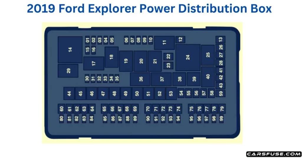
1Micro 2 fuse / 2M-case fuse / 3J-case fuse
| Fuse or Relay Number | Fuse Rating | Protected Component |
| 1 | 20A1 | Powertrain control module power. |
| 2 | 20A1 | Engine emissions (MIL). |
| 3 | 20A1 | A/C clutch control relay coil. Variable Air Conditioning Compressor. Active grille shutters. |
| 4 | 20A1 | Ignition coils. |
| 5 | — | Not used. |
| 6 | — | Not used. |
| 7 | — | Not used. |
| 8 | — | Not used. |
| 9 | — | Not used. |
| 10 | 15A1 | Heated mirrors. |
| 11 | — | Not used. |
| 12 | 40A2 | Heated rear window. |
| 13 | — | Not used. |
| 14 | — | Powertrain control module relay. |
| 15 | 20A1 | Horn relay power. |
| 16 | 10A1 | A/C clutch relay power. |
| 17 | — | Rear heated window and heated mirrors relay. |
| 18 | — | Rear blower motor relay. |
| 19 | — | Not used. |
| 20 | — | Left-hand side cooling fan relay. |
| 21 | — | Cooling fans series/parallel relay. |
| 22 | 25A2 | Electronic fan relay 2. |
| 23 | — | Not used. |
| 24 | — | Right-hand side electronic cooling fan 3 relay. |
| 25 | — | Not used. |
| 26 | 30A2 | Anti-lock brake system valves. |
| 27 | 30A2 | Trailer tow battery charge relay power. |
| 28 | — | Not used. |
| 29 | — | Starter relay. |
| 30 | — | Not used. |
| 31 | 10A1 | Electric power-assisted steering. |
| 32 | 10A1 | Anti-lock brake system module. |
| 33 | 10A1 | Powertrain control module (Ignition Switch Position – Run). |
| 34 | 10A1 | Blind spot information system. Adaptive cruise control. Front view camera. Rear camera. |
| 35 | — | Not used. |
| 36 | — | Blower motor relay. |
| 37 | — | Trailer tow battery charge relay. |
| 38 | — | A/C compressor clutch relay. |
| 39 | — | Horn relay. |
| 40 | — | Not used. |
| 41 | 40A2 | Rear blower motor. |
| 42 | — | Not used. |
| 43 | 40A2 | Front blower motor. |
| 44 | 50A3 | Voltage quality module bus. |
| 45 | 40A3 | Electronic fan relay 1. |
| 46 | 30A3 | Trailer tow brake controller. |
| 47 | — | Not used. |
| 48 | 50A3 | Body control module RP1 bus. |
| 49 | — | Not used. |
| 50 | 50A3 | Body control module RP2 bus. |
| 51 | 50A3 | Electronic fan relay 3. |
| 52 | 60A3 | Anti-lock brake system pump. |
| 53 | — | Not used. |
| 54 | — | Not used. |
| 55 | — | Not used. |
| 56 | 40A2 | Power inverter. |
| 57 | — | Not used. |
| 58 | — | Not used. |
| 59 | — | Not used. |
| 60 | 20A2 | Powerpoint (front console bin). |
| 61 | — | Not used. |
| 62 | 20A2 | Powerpoint (instrument panel). |
| 63 | 30A2 | Fuel pump. |
| 64 | — | Not used. |
| 65 | 20A2 | Powerpoint (2nd row) (without USB charger). |
| 66 | — | Not used. |
| 67 | 20A2 | Powerpoint (cargo area). |
| 68 | — | Not used. |
| 69 | 30A2 | Power liftgate. |
| 70 | 15A2 | Trailer tow left-hand and right-hand stop and direction indicator lamps. |
| 71 | — | Not used. |
| 72 | 30A2 | Heated/cooled seats. |
| 73 | 30A2 | Driver seat module. Driver seat power. |
| 74 | 30A2 | Passenger seat power. |
| 75 | 30A2 | Front wiper motor. |
| 76 | — | Not used. |
| 77 | — | Not used. |
| 78 | 30A2 | 3rd-row power folding seat module relay. |
| 79 | 30A2 | Starter relay. |
| 80 | — | Not used. |
| 81 | 10A1 | Trailer tow backup lamp relay. |
| 82 | 20A2 | Steering column lock (if equipped). |
| 83 | 10A1 | Brake on/off switch. |
| 84 | — | Not used. |
| 85 | 5A1 | 2nd row USB charger (if equipped). |
| 86 | — | Not used. |
| 87 | — | Not used. |
| 88 | — | Not used. |
| 89 | — | Not used. |
| 90 | — | Not used. |
| 91 | — | Not used. |
| 92 | 15A1 | Multi-contour seat module relay. |
| 93 | 10A1 | Alternator sense. |
| 94 | 15A1 | Rear washer relay. |
| 95 | 15A1 | Rear wiper relay. |
| 96 | 10A1 | Powertrain control module relay coil power. |
| 97 | 5A1 | Rain sensor. |
| 98 | 20A1 | 2nd-row seat motors. |
| 99 | 20A1 | Trailer tow parking lamp relay. |
Note: The respective vehicle owner's manual will provide you with the most accurate and up-to-date information. It's important to go through owner's manual for the exact location and identification of the fuse box in your vehicle, as the location can vary slightly depending on the trim level or optional features.
2019 Ford Explorer Fuse Box Diagram (Passenger Compartment Fuse Panel)
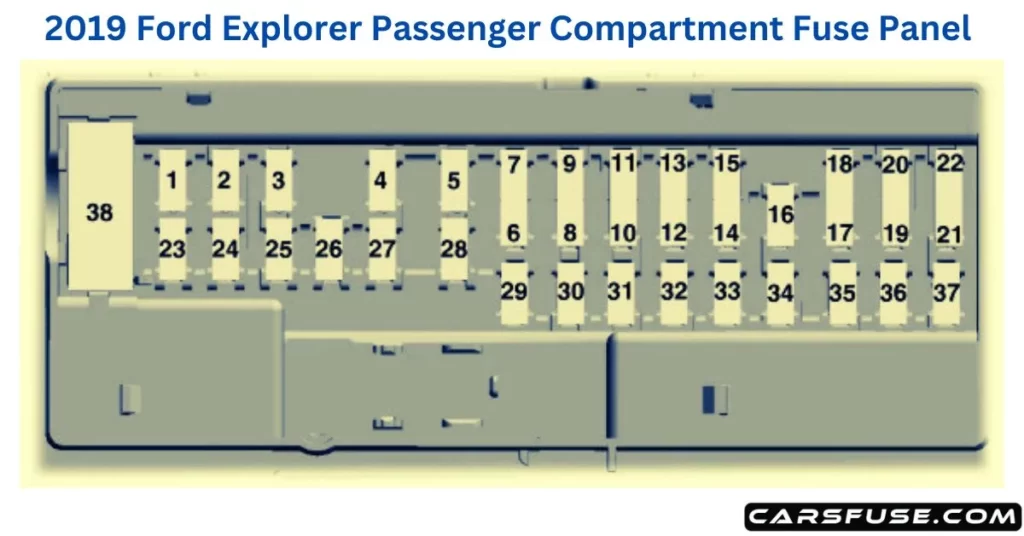
4Micro 2 fuse / 5Micro 3 fuse / 6Circuit breaker
| Fuse or Relay Number | Fuse Rating | Protected Components |
| 1 | — | Not used. |
| 2 | 7.5A4 | Memory seat switch (lumbar power). |
| 3 | 20A4 | Driver unlock relay. |
| 4 | 5A4 | Aftermarket electronic brake controller. |
| 5 | 20A4 | Rear heated seat module. |
| 6 | — | Not used. |
| 7 | — | Not used. |
| 8 | — | Not used. |
| 9 | — | Not used. |
| 10 | 5A5 | Embedded modem. Hands free liftgate. |
| 11 | 5A5 | Rear climate control module. Securicode™ keyless entry keypad. Power liftgate module. |
| 12 | 7.5A5 | Front climate control module. |
| 13 | 7.5A5 | Instrument cluster. Smart data link. Steering column control module. |
| 14 | 10A5 | Extended power module. |
| 15 | 10A5 | Smart datalink connector power. Heads up display. |
| 16 | — | Not used. |
| 17 | 5A5 | Electronic finish panel. |
| 18 | 5A5 | Push button start switch. Ignition switch. Key inhibit. |
| 19 | 7.5A5 | Transmission control switch. |
| 20 | — | Not used. |
| 21 | 5A5 | Terrain management switch. Heads up display. Humidity sensor. |
| 22 | 5A5 | Occupant classification sensor. |
| 23 | 10A4 | Delayed accessory power. Power windows. Moonroof. Folding mirror relay. DC inverter. Window/moonroof switch illumination. |
| 24 | 20A4 | Central lock relay. |
| 25 | 30A4 | Left-hand front smart window motor. Door zone module. |
| 26 | 30A4 | Right-hand front smart window motor. Door zone module. |
| 27 | 30A4 | Moonroof. |
| 28 | 20A4 | Sony amplifier – 10 channel. |
| 29 | 30A4 | Sony amplifier – 14 channel. |
| 30 | — | Not used. |
| 31 | — | Not used. |
| 32 | 10A4 | SYNC module. GPS module. Display. Radio frequency receiver. |
| 33 | 20A4 | Radio. |
| 34 | 30A4 | Starter relay. |
| 35 | 5A4 | Restraints control module. Extended power module. |
| 36 | 15A4 | Lane departure warning module. Auto high beam. EC mirrors. Rear heated seats. |
| 37 | 20A4 | Heated steering wheel. |
| 38 | 30A6 | Left-hand front window motor. Rear power window motors. |
Please click on the link for more information on topic "Can a blown fuse drain a car battery?" to know the role of fuses, identify potential causes of battery drainage, and implement preventive measures, to ensure the longevity of their car batteries.
Tom Smith is a passionate car mechanic and automotive enthusiast, specializing in the intricate world of car fuse boxes. With years of hands-on experience under the hood, he has earned a reputation as a reliable expert in his field. As the founder and content creator of the popular blog website 'carsfuse.com,' Tom has dedicated himself to sharing his extensive knowledge of car fuse boxes and electrical systems with the world.
