
In this blog, you will find an in-depth about the 2016 Ford F150 fuse box diagram. Explaining the functions of each fuse, to make easier for you to understand your vehicle electrical system with confidence and ease.
Table of Contents
Note: If a fuse blows or a circuit breaker opens, all parts connected to that circuit will stop working. Taking the time to inspect and replace faulty fuses can save you from unnecessary repairs and potential hazards, ensuring the smooth operation of your vehicle's electrical components.
2016 Ford F150 Power Distribution Fuse Box Diagram
The power distribution box, which houses high-current fuses, is situated in the engine compartment of your vehicle. These fuses play a crucial role in safeguarding the main electrical systems from overloads, ensuring their proper functioning. The high-current fuses within the power distribution box are coded using a specific system. This coding scheme helps identify and differentiate the various fuses.
Note: In the event that you need to disconnect and reconnect the battery, it's important to note that certain features may require resetting. This step is necessary to restore their functionality.

*Cartridge fuses / **Mini fuses
| Fuse or relay number | Fuse amp rating | Protected components |
| 1 | — | Not used. |
| 2 | — | Not used. |
| 3 | — | Not used. |
| 4 | — | Telescoping side-view mirror. |
| 5 | 40A* | Rear window defroster. |
| 6 | — | Not used. |
| 7 | — | Not used. |
| 8 | — | Telescoping side-view mirror. |
| 9 | — | Not used. |
| 10 | — | Not used. |
| 11 | 60A* | Automatic brake system motor. |
| 12 | 50A* | Body control module 1. |
| 13 | 60A* | Body control module 2. |
| 14 | 20A** | Amplifier. |
| 15 | 25A** | 4×4. |
| 16 | 10A** | Spotlight module. |
| 17 | 15A** | Heated seat. |
| 18 | 10A** | Steering-column lock. |
| 19 | 10A** | Power seats. |
| 20 | 15A** | Snow plow. Rear heated seats. |
| 21A | — | Not used. |
| 21B | — | Not used. |
| 22 | 30A* | Windshield wiper motor. |
| 23 | 15A* | Rain sensor. |
| 24 | 25A* | Series fan feed. |
| 25 | — | Not used. |
| 26 | 30A* | Driver seat motors. |
| 27 | 30A* | Passenger power seat. |
| 28 | 30A* | Climate-controlled seat. |
| 29 | — | Not used. |
| 30 | — | Air conditioner clutch relay. |
| 31 | — | Not used. |
| 32 | — | Not used. |
| 33 | 50A* | Electric fan 3. |
| 34 | 25A* | Trailer tow park lamps. |
| 35 | 20A* | Trailer tow stop-turn relay fuse. |
| 36 | 25A* | Trailer tow lamps module. |
| 37 | 50A* | Electric fan 1. |
| 38 | 10A** | Alt-A sensor. |
| 39 | 10A** | Integrated wheel end solenoid. |
| 40 | 15A** | E-locker. |
| 41 | 10A** | Telescoping mirror. |
| 42 | 30A** | Transmission fluid pump. |
| 43 | 25A** | Horn. |
| 44 | 10A** | Air conditioner clutch. |
| 45 | 10A** | Powertrain control module relay coil. |
| 46 | 10A** | Wiper relay coil. |
| 47 | — | Not used. |
| 48 | — | Not used. |
| 49 | 30A* | Trailer brake control module. |
| 50 | 30A* | Power running boards. |
| 51 | — | Fuel pump relay. |
| 52 | — | Not used. |
| 53 | — | Not used. |
| 54 | 30A* | Voltage quality module. Body-control-module voltage-quality-module feed. |
| 55 | 40A* | Body control module RP2 feed. |
| 56 | 20A* | Fuel pump. |
| 57 | 30A* | Right-hand EPB actuator. |
| 58 | 30A* | Left-hand EPB actuator. |
| 59 | 30A* | Starter. |
| 60 | 40A* | Blower motor. |
| 61 | 30A* | Brake control module. Automatic brake system valves. |
| 62 | — | Power seat relay. |
| 63 | 15A** | Heated mirrors. |
| 64 | — | Not used. |
| 65 | — | Starter relay. |
| 66 | — | Powertrain control module relay. |
| 67 | — | Windshield wiper relay. |
| 68 | — | Blower motor relay. |
| 69 | — | Power sliding back window relay. |
| 70 | — | Electric fan 1 relay. |
| 71 | — | Not used. |
| 72 | 25A* | 4×4. |
| 73 | — | Not used. |
| 74 | 30A* | PDRG motor. |
| 75 | — | Horn relay. |
| 76 | — | Not used. |
| 77 | — | Steering column lock relay. |
| 78 | — | Not used. |
| 79 | — | Trailer tow parking lamp relay. |
| 80 | — | Rear window defroster relay. |
| 81 | — | Not used. |
| 82 | — | PDRG close relay. |
| 83 | — | Not used. |
| 84 | — | Not used. |
| 85 | — | Not used. |
| 86 | — | Not used. |
| 87 | 10A** | Trailer tow backup lamps. |
| 88 | — | Not used. |
| 89 | 20A* | Cigar lighter power point 1. |
| 90 | 20A* | Powerpoint 2. |
| 91 | 20A* | Powerpoint 3. |
| 92 | 20A* | Electric fan 3 relay. |
| 93 | 25A** | GTDI vehicle power 1. |
| 10A** | PFI vehicle power 1. | |
| 94 | — | Not used. |
| 95 | 25A** | Vehicle power 2. |
| 96 | — | Not used. |
| 97 | 10A** | Vehicle power 3. |
| 98 | — | Not used. |
| 99 | 20A** | Vehicle power 4 (PFI). |
| 15A** | Vehicle power 4 (GTDI). | |
| 100 | — | Not used. |
| 101 | — | Not used. |
| 102 | — | Snow plow relay. |
| 103 | — | Not used. |
| 104 | — | Electic fan 3 relay. |
| 105 | 10A** | Power steering. |
| 106 | — | Not used. |
| 107 | 10A** | Anti-lock brakes. |
| 108 | — | Not used. |
| 109 | 10A** | Powertrain control module. |
| 110 | 10A** | 4×4 run/start. Adaptive cruise control. |
| 111 | 10A** | Transmission pump run-start. |
| 112 | — | Not used. |
| 113 | 7.5A** | Blind spot information system. Rearview camera. Front view camera. Voltage quality module. |
| 114 | — | Electric fan 2 relay. |
| 115 | — | Not used. |
| 116 | — | Not used. |
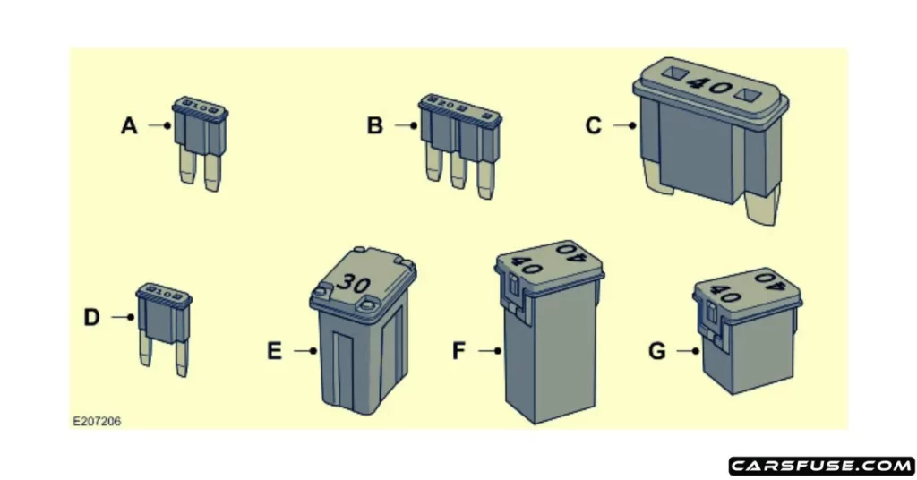
| Callout | Fuse Type |
|---|---|
| A | Micro 2 |
| B | Micro 3 |
| C | Maxi |
| D | Mini |
| E | M Case |
| F | J Case |
| G | J Case Low Profile |
2016 Ford F150 Passenger Compartment Fuse Panel
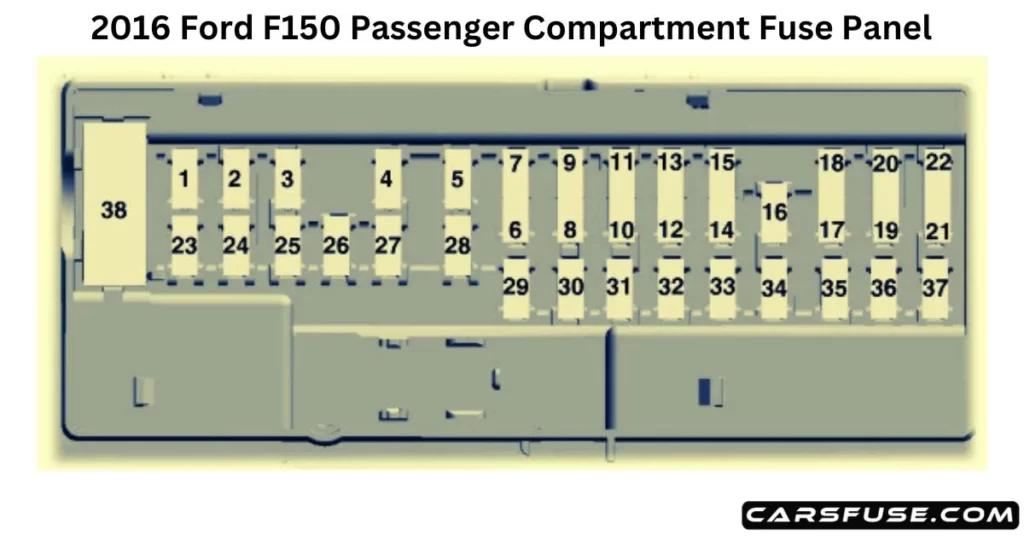
| Fuse or relay number | Fuse amp rating | Protected components |
| 1 | 10A | Demand lamp relay. Power seat relay. Glove box. Vanity lamps. Overhead console. Dome. Courtesy. Map lamps. |
| 2 | 7.5A | Memory module logic. Memory seat switches. Lumbar motor. |
| 3 | 20A | Driver door lock motor. |
| 4 | 5A | Trailer brake control. |
| 5 | 20A | Not used. |
| 6 | 10A | Not used. |
| 7 | 10A | Not used. |
| 8 | 10A | Not used. |
| 9 | 10A | Not used. |
| 10 | 5A | Not used (spare). |
| 11 | 5A | Combined sensor module. |
| 12 | 7.5A | Climate head module. Smart datalink converter. |
| 13 | 7.5A | Cluster. SCCM. |
| 14 | 10A | Brake. |
| 15 | 10A | Smart datalink converter. |
| 16 | 15A | Tailgate release. |
| 17 | 5A | HUD. |
| 18 | 5A | Ignition switch and passive-entry passive-start start stop switch. Key inhibit solenoid. |
| 19 | 7.5A | Tow haul (O/D) cancel for floor or column shifter. |
| 20 | 7.5A | Not used. |
| 21 | 5A | Ignition switch and passive-entry passive-start start-stop switch. Key inhibit solenoid. |
| 22 | 5A | EPB. Power seat. |
| 23 | 10A | PDRG switch. Inverter. Driver-side window. Moonroof. Vista roof. |
| 24 | 20A | Central lock/unlock. |
| 25 | 30A | Driver door control module. |
| 26 | 30A | Passenger door control module. |
| 27 | 30A | Vista roof. Moonroof. |
| 28 | 20A | Not used. |
| 29 | 30A | Not used. |
| 30 | 30A | Not used. |
| 31 | 15A | Adjustable pedal switch and motor. |
| 32 | 10A | Multi-function display. Global position system. Sync 1. Sync 2. Radio frequency receiver. |
| 33 | 20A | Radio. |
| 34 | 30A | Run-start relay. |
| 35 | 5A | Restraints module. |
| 36 | 15A | 360 camera module. Heated steering wheel module. Rear-view mirror. Rear heated seats. |
| 37 | 20A | Power distribution box run-start fuses. |
| 38 | 30A Circuit breaker. | Rear window switches and motors. |
To provide a comprehensive guide on "How to read a car fuse box diagram?" please click the link. It aims to help readers gain the knowledge and skills needed to interpret these diagrams correctly. By understanding car fuse diagrams, readers can confidently locate fuses, determine their functions, and troubleshoot electrical problems in their vehicles.
Tom Smith is a passionate car mechanic and automotive enthusiast, specializing in the intricate world of car fuse boxes. With years of hands-on experience under the hood, he has earned a reputation as a reliable expert in his field. As the founder and content creator of the popular blog website 'carsfuse.com,' Tom has dedicated himself to sharing his extensive knowledge of car fuse boxes and electrical systems with the world.
