In this article, on the 2013 Ford Expedition Fuse box diagram we provide you with an essential information and guide for the fuse box.
When faced with electrical problems in your Ford Expedition , having a reliable resource is essential. With our detailed explanations, you’ll be able to navigate the complex web of fuses and relays, diagnosing and resolving issues with ease.
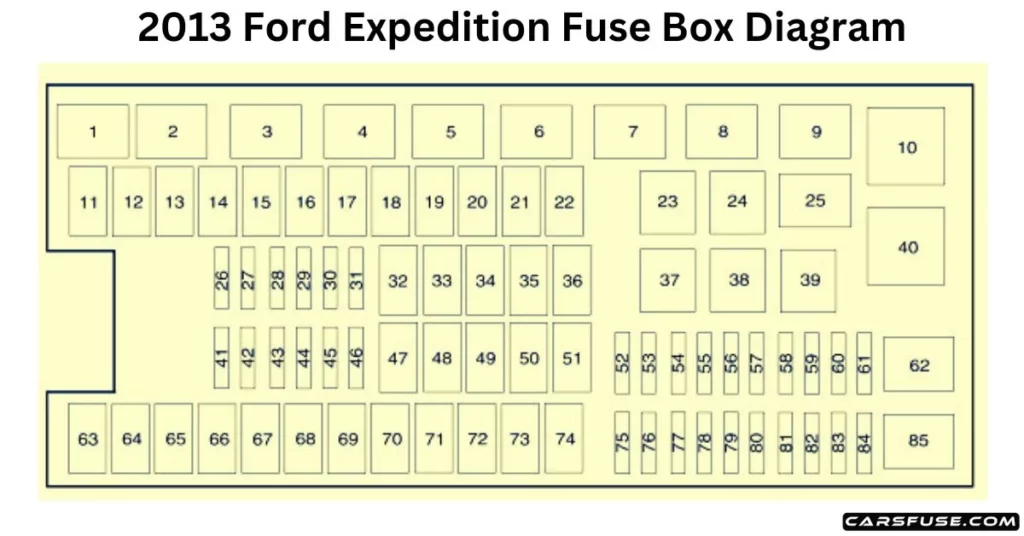
Note: All information contained in this Quick Reference Guide was accurate at the time of duplication. For detailed operating and safety information, please consult your Owner’s Manual 2013 Ford Expedition Fuse Box Diagram POWER DISTRIBUTION BOX 2013 FORD EXPEDITION FUSE BOX DIAGRAM Note: In the event that you need to disconnect and reconnect the battery, it's important to note that certain features may require resetting. This step is necessary to restore their functionality. * Mini Fuses / ** Cartridge Fuses
Spare fuse amperage may vary. Fuse or relay location Fuse amp rating Protected circuits 1 — Powertrain control module relay 2 — Starter relay 3 — Blower motor relay 4 — Trailer tow battery charge relay 5 — Fuel pump relay 6 — Electronic fan 1 relay 7 — Rear window defroster/heated mirror relay 8 — Electronic fan 3 relay 9 — Run/start relay 10 — Rear air suspension relay 11 40A** Power running board 12 40A** Run/start relay 13 30A ** Starter relay 14 40A** Electronic fan 15 — Not used 16 40A** Electronic fan 17 — Not used 18 30A** Trailer brake 19 60A** Rear air suspension relay feed 20 20A** 4×4 module 21 30A** Trailer tow battery charge relay 22 30A** Passenger power seat 23 — A/C clutch relay 24 — Trailer tow park lamp relay 25 — Not used 26 — Not used 27 20A* 4×4 28 25A* Trailer tow park lamp relay 29 20A* Backup lamps, Integrated wheel end solenoid 30 10A* A/C clutch relay 31 — Not used 32 40A** Blower motor relay 33 40A** 110-volt AC powerpoint 34 30A** Auxiliary blower motor 35 30A** Powertrain control module relay 36 30A** Power liftgate 37 — Trailer tow left-hand stop/turn relay 38 — Trailer tow right-hand stop/turn relay 39 — Backup lamps relay 40 — Electronic fan 2 relay 41 10A* Powertrain control module keep-alive power 42 — Not used 43 5A* Brake on/off switch 44 20A* Fuel pump relay 45 25A* Trailer tow stop/turn lamps relay 46 — Not used 47 — Not used 48 30A** Rear air suspension module 49 — Not used 50 30A** Front wiper motor relay 51 40A** Rear window defroster/heated mirror relay 52 10A* Anti-lock brake system run/start feed 53 10A* Rear air suspension module 54 — Not used 55 5A* Fuel pump relay coil run/start feed 56 30A* Passenger compartment fuse panel R/S feed 57 10A* Blower motor relay coil 58 15A* Trailer tow backup lamps 59 15A* Heated mirrors 60 — Not used 61 — Fuel pump diode 62 — Not used 63 25A** Electronic fan 64 30A** Moon roof 65 20A** Auxiliary power point (instrument panel) 66 20A** Auxiliary power point (rear of center console) 67 40A** Front row climate controlled seats 68 60A** Anti-lock brake system valves 69 60A** Anti-lock brake system pump 70 30A** Third-row power fold seat 71 20A** Auxiliary power point/cigar lighter 72 20A** Auxiliary power point (right rear quarter panel) 73 — Not used 74 30A** Driver power seat 75 20A* Vehicle power 1 – powertrain control module 76 20A* Vehicle power 2 – powertrain control module 77 15A* Vehicle power 4 – ignition coils 78 — Not used 79 20A* Vehicle power 3 – powertrain control module 80 — Not used 81 — Not used 82 — Not used 83 — Not used 84 — Not used 85 — Wiper motor relay
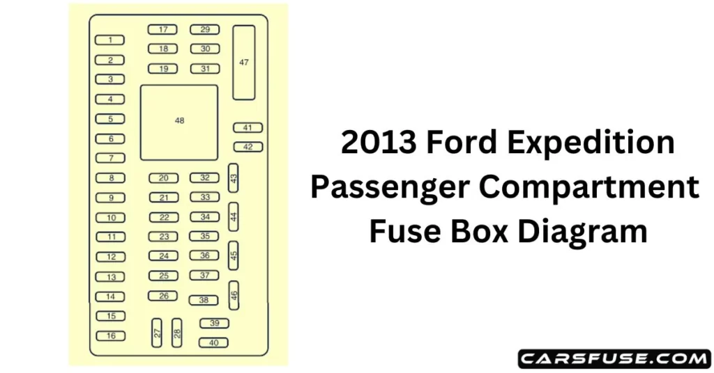
PASSENGER COMPARTMENT FUSE PANEL 2013 FORD EXPEDITION FUSE BOX DIAGRAM Fuse or relay location Fuse amp rating Protected circuits 1 30A Driver window 2 15A Driver-side memory module 3 15A Audio rear seat controls, Satellite radio, SYNC 4 30A Not used (spare) 5 10A Keypad illumination, 3rd-row seat enable, Brake shift interlock, Smart fuse panel logic power 6 20A Turn signals 7 10A Low beam headlamps (left) 8 10A Low beam headlamps (right) 9 15A Interior lights 10 15A Switch backlighting, Puddle lamps 11 10A Not used (spare) 12 7.5A Power mirrors, Driver seat memory switch 13 5A Not used (spare) 14 10A Power liftgate module – keep-alive power 15 10A Climate control, Global positioning satellite module 16 15A Not used (spare) 17 20A Door locks, Liftgate release, Liftglass release 18 20A Second-row heated seats 19 25A Rear wiper 20 15A Adjustable pedals, Datalink 21 15A Fog lamps 22 15A Park lamps 23 15A High beam headlamps 24 20A Horn 25 10A Demand lamps, Glove box, Visor 26 10A Instrument panel cluster 27 20A Ignition switch 28 5A Radio 29 5A Instrument panel cluster 30 5A Not used (spare) 31 10A Not used (spare) 32 10A Airbag module 33 10A Trailer brake logic 34 5A Not used (spare) 35 10A Rear park assist, 4×4, rear video camera, 2nd row heated seats 36 5A Passive anti-theft system 37 10A Climate control 38 20A Subwoofer 39 20A Radio 40 20A Navigation amplifier 41 15A Power windows, Power vents, Power moonroof, Auto dimming rear view mirror, 110 volt AC powerpoint 42 10A Not used (spare) 43 10A Rear wiper logic, Rain sensor 44 10A Trailer tow battery charge relay coil 45 5A Front wiper logic 46 7.5A Climate control, Auxiliary relay control 47 30A Circuit Breaker Power windows, Moonroof 48 — Delayed accessory relay
2013 Ford Expedition Standard Fuse Amperage Rating and Color Fuse rating Mini fuses Standard fuses Maxi fuses Cartridge maxi fuses Fuse link cartridge 2A Grey Grey — — — 3A Violet Violet — — — 4A Pink Pink — — — 5A Tan Tan — — — 7.5A Brown Brown — — — 10A Red Red — — — 15A Blue Blue — — — 20A Yellow Yellow Yellow Blue Blue 25A Natural Natural — Natural Natural 30A Green Green Green Pink Pink 40A — — Orange Green Green 50A — — Red Red Red 60A — — Blue Yellow Yellow 70A — — Tan — Brown 80A — — Natural Black Black