
In this article, learn more about the 2010 Ford F150 fuse box diagram, its location, and function.
The fuse box is responsible for protecting the electrical circuits from overloading and damage. This quick reference guide is not intended to replace your vehicle Owner’s Manual which contains more detailed information concerning the features of your vehicle, as well as important safety warnings designed to help reduce the risk of injury to you and your passengers.
Table of Contents
Note: All information contained in this Quick Reference Guide was accurate at the time of duplication. For detailed operating and safety information, please consult your Owner’s Manual.
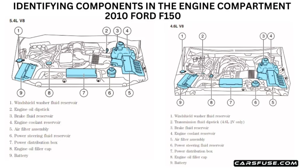
2010 Ford F150 Power Distribution Box Diagram
The power distribution box is located in the engine compartment. It has high-current fuses that protect your vehicle’s main electrical systems from overloads. If you disconnect and reconnect the battery, you will need to reset some features. The high-current fuses are coded as follows:
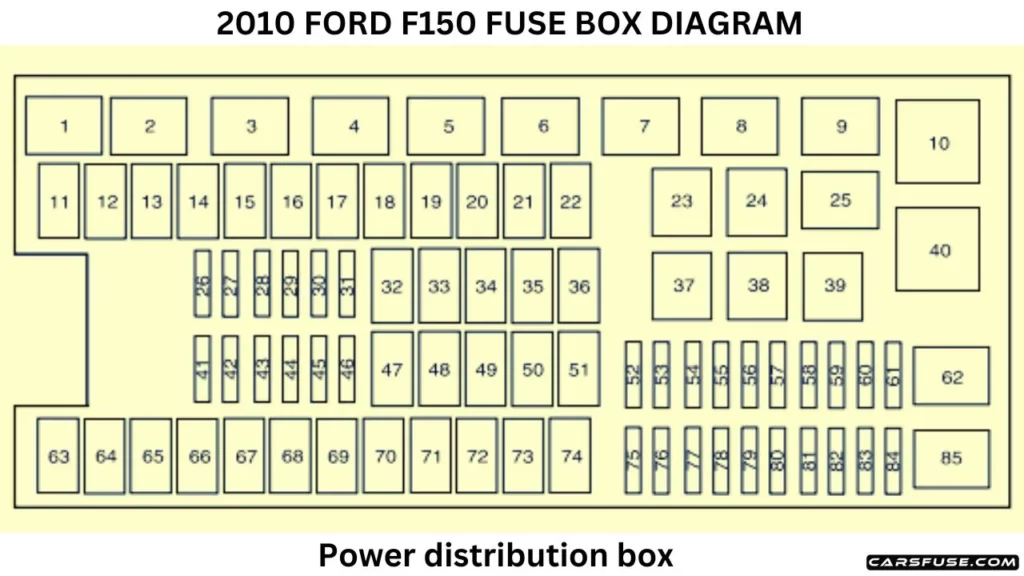
(*Mini fuses / **Cartridge fuses)
| Fuse or relay number | Fuse amp rating | Protected Circuits |
| 1 | – | Powertrain control module (PCM) power relay |
| 2 | – | Starter relay |
| 3 | – | Blower motor relay |
| 4 | – | Rear window defroster |
| 5 | – | Electric fan relay (high speed) |
| 6 | – | Trailer tow park lamp relay |
| 7 | – | Upfitter 1 relay |
| 8 | – | Fuel pump |
| 9 | – | Trailer tow battery charger |
| 10 | – | Upfitter 2 relay |
| 11 | 30A** | Power running board motors |
| 12 | 40A** | Electric fan |
| 13 | 30A** | Starter relay power |
| 14 | 30A** | Passenger power seat |
| 15 | 40A* * | Electric fan |
| 16 | – | Not Used |
| 17 | 30A** | Trailer brake control |
| 18 | 30A** | Upfitter 1 |
| 19 | 30A** | Upfitter 2 |
| 20 | 20A** | 4×4 module (ESOF) |
| 21 | 30A* * | Trailer tow battery charge |
| 22 | 20A** | Cigar lighter |
| 23 | – | Air conditioner clutch relay |
| 24 | – | Upfitter 4 relay |
| 25 | – | Heated mirror relay |
| 26 | 10A* | PCM – keep alive power, Canister vent solenoid, Transmission, PCM relay |
| 27 | 20A* | Fuel pump relay |
| 28 | 10A* | Upfitter 4 |
| 29 | 10A* | 4×4 integrated wheel end solenoid |
| 30 | 10A* | Air conditioner clutch relay power |
| 31 | 15A* | Trailer tow park lamp relay |
| 32 | 40A** | Heated backlite |
| 33 | – | Not Used |
| 34 | 40A** | Powertrain control module relay power |
| 35 | – | Not Used |
| 36 | 30A** | Roll stability control module (RSC) |
| 37 | – | Trailer tow left hand stop/turn relay |
| 38 | – | Trailer tow right-hand stop/turn relay |
| 39 | – | Backup lamp relay power |
| 40 | – | Electric fan relay |
| 41 | 15A* | Heated Mirror |
| 42 | – | Not Used |
| 43 | 20A* | Backup lamp relay |
| 44 | 15A* | Upfitter 3 |
| 45 | 20A* | Trailer tow stop turn relay feed |
| 46 | 15A* | Brake on/off (BOO) switch |
| 47 | 60A** | Roll stability control module (RSC) |
| 48 | – | Not Used |
| 49 | 30A** | Wiper relay power |
| 50 | – | Not used |
| 51 | 40A** | Blower motor relay power |
| 52 | – | Not used |
| 53 | 5A* | PCM, 6R80 transmission |
| 54 | 5A* | 4×4 module, Back up lamp, RSC, Trailer tow battery charge relay |
| 55 | 5A* | Electronic compass mirror (6R transmission only) |
| 56 | – | Not Used |
| 57 | – | Not used |
| 58 | 15A* | Trailer tow backup lamps |
| 59 | – | Not used |
| 60 | – | One-touch Start diode |
| 61 | – | Fuel pump diode |
| 62 | – | Upfitter 3 relay |
| 63 | 25A** | Electric fan relay power |
| 64 | 30A** | Amplifier |
| 65 | 20A** | Auxiliary power point (instrument panel) |
| 66 | 20A** | Auxiliary power point (inside center console) |
| 67 | – | Not Used |
| 68 | 20A** | 4×4 module |
| 69 | 30A** | Passenger heated/cooled seats |
| 70 | – | Not used |
| 71 | – | Not used |
| 72 | 20A** | Auxiliary power point (rear) |
| 73 | – | Not Used |
| 74 | 30A** | Driver power seat |
| 75 | 15A* | Powertrain control module – voltage power 1 |
| 76 | 20A* | Voltage power 2, Voltage – battery voltage, Mass air flow/Intake air temp, CMS 12 and 22 with 6R80 transmission, Brake on/off switch (BOO) |
| 77 | 10A* | Voltage power 3, Electric fan clutch, A/C clutch relay coil, Floor shifter (4–speed transmission) |
| 78 | 15A* | Ignition coils, Voltage power 4 |
| 79 | 10A* | CMS 4–speed transmission, 12 and 22 with 4–speed transmission |
| 80 | 5A* | Steering wheel illumination |
| 81 | – | Not used |
| 82 | 10A* | Trailer brake control module (TBCM), After market center high mounted stop lamp (CHMSL) |
| 83 | – | Not used |
| 84 | – | Not used |
| 85 | – | Electric fan relay (low speed) |
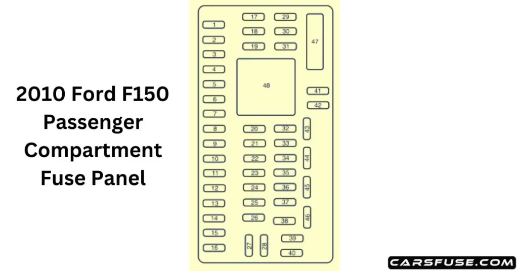
2010 Ford F150 Passenger Compartment Fuse Panel
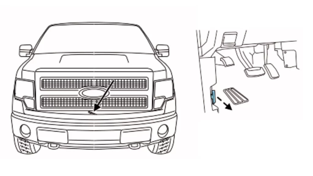
The fuse panel is on the right-hand side of the passenger footwell behind a trim panel. To remove the fuse panel cover, press the tabs on both sides of the cover, and then pull it off. To reinstall the fuse panel cover, place the top part of the cover on the fuse panel and push the bottom part until it latches. Gently pull on the cover to make sure it has latched properly.
| Fuse or relay number | Fuse amp rating | Protected Circuits |
| 1 | 30A | Moon roof |
| 2 | 15A | Not used (spare) |
| 3 | 15A | Not used (spare) |
| 4 | 30A | Not used (spare) |
| 5 | 10A | Keypad illumination, Brake Shift Interlock (BSI), SJB microprocessor power |
| 6 | 20A | Turn signals, Stop lamps |
| 7 | 10A | Low beam headlamps (left) |
| 8 | 10A | Low beam headlamps (right) |
| 9 | 15A | Interior courtesy lights, Cargo lamps |
| 10 | 15A | Backlighting, Puddle lamps |
| 11 | 10A | GPS module |
| 12 | 7.5A | Power mirror switch, Memory seat module microprocessor power, Steering column switch |
| 13 | 5A | SYNC |
| 14 | 10A | Ambient lighting module |
| 15 | 10A | Climate control |
| 16 | 15A | Ignition switch feed |
| 17 | 20A | All lock motor feeds |
| 18 | 20A | Driver memory seat switch |
| 19 | 25A | Not used (spare) |
| 20 | 15A | Adjustable pedals, Datalink |
| 21 | 15A | Fog lamps, Fog lamp indicator |
| 22 | 15A | Park lamps, Side marker lamps |
| 23 | 15A | High beam headlamps |
| 24 | 20A | Horn |
| 25 | 10A | Interior demand lamps, Mid box power feed |
| 26 | 10A | Instrument panel cluster, Key out inhibit solenoid, Radio info display (CID), Radio buttons, Key-in chime |
| 27 | 20A | Not used |
| 28 | 5A | Radio muting |
| 29 | 5A | Instrument panel cluster |
| 30 | 5A | Passenger airbag disable indicator |
| 31 | 10A | Passenger airbag disabled indicator |
| 32 | 10A | Non-integrated compass module, Heated-only seat module |
| 33 | 10A | Trailer brake controller |
| 34 | 5A | Electronic locking differential indicator |
| 35 | 10A | Reverse sensing system |
| 36 | 5A | Passive anti-theft system transceiver |
| 37 | 10A | Upfitter relay coils |
| 38 | 20A | Subwoofer |
| 39 | 20A | Radio, Navigation display |
| 40 | 20A | Auto-dimming rearview mirror, Door lock switch illumination, Radio accessory delay |
| 41 | 15A | Auto-dimming rear view mirror, Door lock switch illumination, Radio accessory delay |
| 42 | 10A | Not used (spare) |
| 43 | 10A | Heated mirror/backlight relay, Rain sensor, Reverse camera |
| 44 | 10A | Not used (spare) |
| 45 | 5A | Front wiper logic, Blower motor relay |
| 46 | 7.5A | Occupant classification sensor (OCS) |
| 47 | 30A Circuit Breaker | Power windows, Moon roof, Power sliding backlight |
| 48 | 15A | Delayed accessory relay (Feeds fuse 41 and circuit breaker 47) |
2010 Ford F150 Standard Fuse Amperage Rating and Color
| Fuse rating | Mini fuses | Standard fuses | Maxi fuses | Cartridge maxi fuses | Fuse link cartridge |
| 2A | Grey | Grey | – | – | – |
| 3A | Violet | Violet | – | – | – |
| 4A | Pink | Pink | – | – | – |
| 5A | Tan | Tan | – | – | – |
| 7.5A | Brown | Brown | – | – | – |
| 10A | Red | Red | – | – | – |
| 15A | Blue | Blue | – | – | – |
| 20A | Yellow | Yellow | Yellow | Blue | Blue |
| 25A | Natural | Natural | – | – | – |
| 30A | Green | Green | Green | Pink | Pink |
| 40A | – | – | Orange | Green | Green |
| 50A | – | – | Red | Red | Red |
| 60A | – | – | Blue | Yellow | Yellow |
| 70A | – | – | Tan | – | Brown |
| 80A | – | – | Natural | Black | Black |
Tom Smith is a passionate car mechanic and automotive enthusiast, specializing in the intricate world of car fuse boxes. With years of hands-on experience under the hood, he has earned a reputation as a reliable expert in his field. As the founder and content creator of the popular blog website 'carsfuse.com,' Tom has dedicated himself to sharing his extensive knowledge of car fuse boxes and electrical systems with the world.
