
In this comprehensive guide, we will explore the 2003 Ford Expedition fuse box diagram, providing you with an overview of the fuse box layout and its associated components. Explaining the functions of each fuse, to make it easier for you to understand your vehicle’s electrical system, and empowering you with the knowledge to troubleshoot electrical issues.
Table of Contents
Note: All information contained in this Quick Reference Guide was accurate at the time of duplication. For detailed operating and safety information, please consult your Ford Expedition Owner’s Manual.
2003 Ford Expedition Fuse Box Diagram Chart
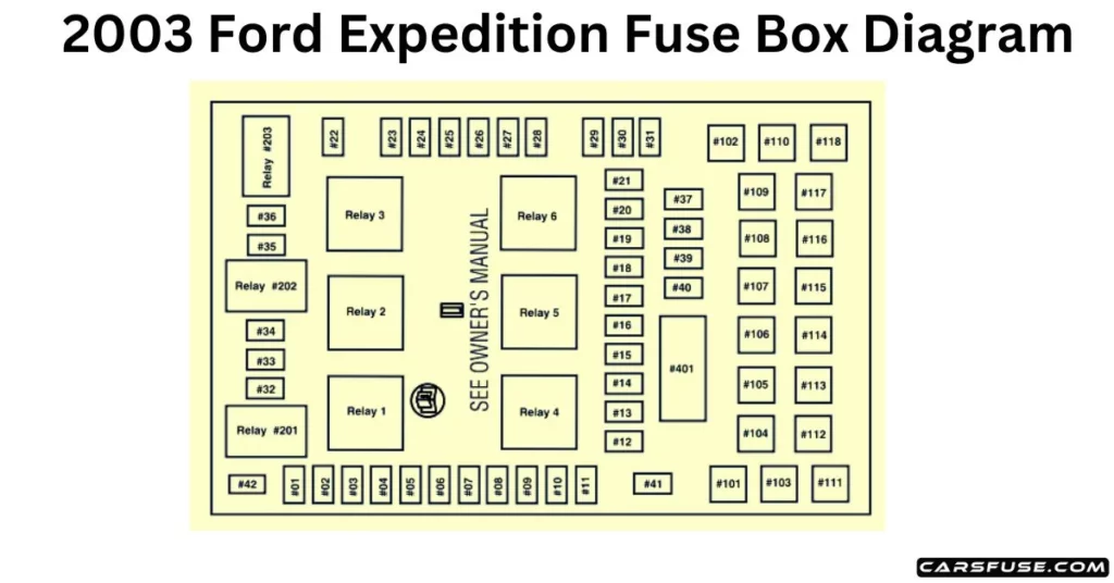
The fuses are coded as follows.
* Mini Fuses / ** Maxi Fuses
| Fuse/RelayLocation | Fuse AmpRating | Passenger Compartment FusePanel Description |
| 1 | 10A* | Run/Accessory – Front wiper motor, Instrument cluster, Rear wiper motor, Tire Pressure Monitor System (TPMS) module |
| 2 | 20A* | Turn signal/Hazard flasher, Stop lamp switch, IVD(AdvanceTrac) stop lamps relay, Stoplamps, Center high-mount stop light (CHMSL), Turn signal lamps |
| 3 | 7.5A* | Power mirror switch, Power mirrors (non-memory), Driver seat switch (memory), Memory module (logic power) |
| 4 | 15A* | DVD player, Rear seat audio controls, CDDJ (navigation radio) |
| 5 | 7.5A* | Powertrain Control Module (PCM) (KA power), Speed control deactivation switch, Manual climate control mode switch, Stoplamp switch, Brake-shift interlock (BSI) solenoid, EATC control head, Body Security Module (BSM) (KA power), Speed control servo, 3rd-row seat relay coils, SecuriLock LED |
| 6 | 15A* | Headlamp switch (park lamps and switch backlight feed), Parklamps, License plate lamps, Foglamp relay coil, Trailer tow electric brake controller (illumination), BSM (auto lamp, park lamps)Foglamp indicator |
| 7 | 7.5A* | Radio (start signal) |
| 8 | 10A* | Rear window defroster switch, Rear window defroster indicator (climate control head), Heated outside mirrors |
| 9 | — | Not used |
| 10 | 20A* | Trailer tow back-up lamps relay, Trailer tow 7–wire connector (back-up lamps), Trailer tow park lamp relay, Trailer tow 7– and 4–pin connectors (park lamps) |
| 11 | 10A* | A/C compressor clutch relay, A/C compressor clutch solenoid, Air suspension compressor relay, 4×4 Integrated Wheel Ends (IWE) solenoid |
| 12 | 10A* | Speed control servo, Speed control relay |
| 13 | 10A* | Manual climate control mode switch, Rear window defroster relay coil, A/C refrigerant containment switch, A/C compressor thermistor, DEATC control head, DEATC solenoids, DEATC blower control, Trailer tow battery charge relay coil |
| 14 | 10A* | Daytime Running Lamps (DRL)ignition relay coil, DigitalTransmission Range Sensor (DTRS) back-up lamps, Trailer tow backup lamps relay coil, Electrochromatic mirror, Navigation radio, Manual A/C blend door actuator |
| 15 | 5A* | AdvanceTrac switch, Instrument cluster (Run/Start feed) |
| 16 | 10A* | ABS/AdvanceTrac module(Run/Start feed) |
| 17 | 15A* | Foglamps |
| 18 | 10A* | Auxiliary A/C temperature blend door actuator, Auxiliary A/C front auxiliary control, Turn signal flasher, Electrochromatic mirror, Auxiliary mode motor, Climate controlled seat modules |
| 19 | 10A* | Restraints Control Module (RCM) |
| 20 | 30A* | Air suspension module (air spring solenoids and height sensors), 4×4 module |
| 21 | 15A* | Instrument cluster (B+), Interior(courtesy) lamps, Puddle lamps(outside mirrors), Tire Pressure Monitoring System (TPMS) module |
| 22 | 10A* | Moonroof switch illumination, Radio (delayed accessory feed), Flip window switch, Flip window motors, EHAM antenna amplifier(navigation radio) |
| 23 | 10A* | RH low beam |
| 24 | 15A* | Interior demand lamps (front map/dome lamp, 2nd-row dome/map lamp, glove compartment lamp, cargo lamp, roof rail lamps, vanity mirror lamps), Battery saver relay coil, Battery saver relay power |
| 25 | 10A* | LH low beam |
| 26 | 20A* | Horn relay, Horns |
| 27 | 5A* | Compass module, Reverse sensing system module, Brake shift interlock (BSI) solenoid, Overdrive cancel switch, Air suspension module (Run/Start sense) |
| 28 | 5A* | PCM relay coil, Speed control relay coil, SecuriLock transceiver |
| 29 | 30A* | Trailer tow electric brake controller, Trailer tow 7–wire connector (electric brake) |
| 30 | 30A* | BSM (door locks, liftgate glass release relay), Liftgate glass release motor, Door/Liftgate lock motors |
| 31 | 25A* | Radio (B+), Subwoofer |
| 32 | 15A* | Catalyst Monitor Sensors (CMS), Transmission solenoids |
| 33 | 20A* | Canister vent solenoid, HEGO sensors, VMV solenoid, Intake Manifold Tuning Valve (IMTV-4.6L engine) solenoid, A/C compressor clutch relay coil, EGR vacuum regulator (EVR) solenoid |
| 34 | 20A* | PCM, Fuel injectors, Fuel pump relay, Fuel pump shut-off switch, Fuel pump motor, Idle air control(IAC) solenoid, Mass Air Flow(MAF) sensor |
| 35 | 20A* | Instrument cluster high beam indicator, High beam headlamps |
| 36 | 10A* | Trailer tow right turn/stop lamps |
| 37 | 20A* | Cargo area powerpoint |
| 38 | 25A* | Rear wiper motor, Washer pump(rear window wash) |
| 39 | 20A* | Console power points (front and rear of console), Instrument panel powerpoint (bench seat) |
| 40 | 20A* | DRL relays, DRL foglamps, DRL headlamp relay coil, Headlamp switch (headlamps), Multifunction switch (flash-to-pass), BSM (auto lamp headlamps relay), High beam relay coil, Fuse 25 (LH low beam), Fuse 23 (RH low beam) |
| 41 | 20A* | Cigar lighter, OBD II diagnostic connector |
| 42 | 10A* | Trailer tow left turn/stop lamps |
| 101 | 30A** | Starter motor relay, Starter motor solenoid |
| 102 | 30A** | Ignition switch power |
| 103 | 30A** | ABS/AdvanceTrac module(pump motor) |
| 104 | 30A** | LH 3rd row seat relay, LH 3rd row seat switch, LH 3rd row seat motor |
| 105 | 40A** | Spare |
| 106 | 30A** | Trailer tow battery charge relay, Trailer tow 7–way connector(battery charge) |
| 107 | 30A** | Auxiliary A/C blower relay,Auxiliary A/C blower motor |
| 108 | 30A** | Passenger seat motor switch |
| 109 | 30A** | Driver seat motor switch(non-memory), Memory module, Power memory mirrors, Adjustable pedals switch, and motor |
| 110 | 30A** | Spare |
| 111 | 50A** | Air suspension compressor, Air suspension compressor relay |
| 112 | 30A** | ABS/AdvanceTrac module(valves) |
| 113 | 30A** | Front wiper motor, Washer pump(windshield wash) |
| 114 | 40A** | Rear window defroster relay, Rear window defroster grid, Heated mirrors (Fuse 8) |
| 115 | 30A** | 4×4 module, Transfer case shift motor |
| 116 | 40A** | Front blower motor relay, Front blower motor |
| 117 | 30A** | RH 3rd row seat relay, RH 3rd row seat switch, RH 3rd row seat motor |
| 118 | 30A** | Driver and passenger climate control seat module |
| 401 | 30A** | Power windows (circuit breaker), Main window switch, Window motors, Window switches, Moonroof module |
| R01 | Starter relay | Starter motor solenoid |
| R02 | Delayed accessory relay | Fuse 22, CB 401, Power windows, Switch backlighting, Radio, Moonroof, Flip windows, DVD, Navigation antenna amplifier |
| R03 | Hi-beam relay | Fuse # 35, Hi-beam headlamps, Hi-beam indicator |
| R04 | Rear window defrost relay | Fuse 8 (heated mirrors), Rear window defroster, Heated outside mirrors, Rear window defroster indicator (climate control head) |
| R05 | Trailer tow battery charge relay | Trailer tow 7–wire connector(battery charge) |
| R06 | Front blower relay | Front blower motor |
| R201 | Trailer tow park lamp relay | Trailer tow 7–wire and 4–wire connectors (park lamps) |
| R202 | Foglamp relay | Front fog lamps |
| R203 | PCM relay | Fuse 32, Fuse 33, Fuse 34, Fuel pump relay, Fuel pump, PCM solenoids, and sensors |
| R301 | Trailer tow backup lamp relay | Trailer tow 7–wire connector(backup lamps) |
| R302 | Speed control relay | Speed control servo |
| R303 | Fuel pump relay | Fuel pump shut-off switch, PCM(fuel pump monitor), Fuel pump |
| R304 | Battery saver relay | Roof rail lamps, Vanity mirror lamps, Map/Dome lamp, Glove box lamp, Cargo area lamp, Outside mirror puddle lamps, Instrument cluster (interior lamps) |
| R305 | Horn relay | Dual note horn |
2003 Ford Expedition Standard fuse amperage rating and color
| Fuse rating | Mini fuses | Standard fuses | Maxi fuses | Cartridge maxi fuses | Fuse link cartridge |
| 2A | Grey | Grey | — | — | — |
| 3A | Violet | Violet | — | — | — |
| 4A | Pink | Pink | — | — | — |
| 5A | Tan | Tan | — | — | — |
| 7.5A | Brown | Brown | — | — | — |
| 10A | Red | Red | — | — | — |
| 15A | Blue | Blue | — | — | — |
| 20A | Yellow | Yellow | Yellow | Blue | Blue |
| 25A | Natural | Natural | — | — | — |
| 30A | Green | Green | Green | Pink | Pink |
| 40A | — | — | Orange | Green | Green |
| 50A | — | — | Red | Red | Red |
| 60A | — | — | Blue | — | Yellow |
| 70A | — | — | Tan | — | Brown |
| 80A | — | — | Natural | — | Black |