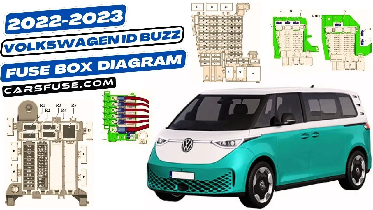
The Volkswagen ID Buzz is an all-electric minivan that was first released in 2022. It is based on the Volkswagen MEB platform, which is also used for the Volkswagen ID.4 and ID.5 electric cars. The ID Buzz is available in two configurations: a passenger van and a cargo van.
The fuses in the Volkswagen ID Buzz are labelled with a number and a letter. The number indicates the amperage of the fuse, and the letter indicates the circuit that the fuse protects. The fuse box diagrams in the owner’s manual provide more detailed information about the fuses and their corresponding circuits.
Table of Contents
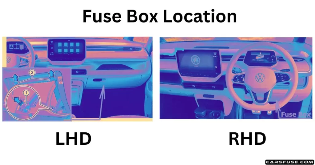
The Volkswagen ID Buzz has two fuse boxes: one in the passenger compartment and one in the engine compartment. The fuse box in the passenger compartment is located under the dashboard, on the driver’s side. The fuse box in the engine compartment is located on the passenger side, near the front of the engine.
Left-hand drive vehicles: In case there are items inside, make sure to empty the contents of the glove box. To proceed, lift the restrictor upwards and remove it from its position. As you do this, you’ll notice catches on either side of the glove box – press them both upwards following the arrow’s direction. While you’re pressing the catches, gently open the glove box even further. This will allow you to access the interior more easily and carry out any necessary tasks.
Right-hand drive vehicles: Gently unlock and swing open the protective cover located on the right-hand side of the steering column. Lower the cover smoothly to reveal its contents. This action grants you access to the concealed components within, allowing you to perform any required actions or maintenance with ease.
Volkswagen ID Buzz Fuse Box Diagram (Instrument Panel)

| Fuse Number | Fuse Amp. Rating | Function / component |
|---|---|---|
| SC1 | 60A | Brake servo |
| SC2 | 15A | Airbag control unit |
| SC3 | 25A | Onboard supply control unit |
| SC4 | 30A | Front left windscreen wiper motor |
| SC5 | 30A | Front right windscreen wiper motor |
| SC6 | 25A | Onboard supply control unit |
| SC7 | 30A | Heater and air conditioning system control unit |
| SC8 | 20A | 12V socket (Cargo version) 12V socket 4 (Cargo version) |
| SC9 | 30A | Driver door control unit (LHD) Front passenger door control unit (RHD) |
| SC10 | 25A | Front left headlight |
| SC11 | 25A | Front right headlight |
| SC12 | 40A | Heated windscreen relay Heated windscreen Left heating circuit |
| SC13 | 40A | Onboard supply control unit |
| SC14 | 50A | ABS control unit |
| SC15 | – | – |
| SC16 | – | – |
| SC17 | 20A | Cigarette lighter, sockets |
| SC18 | 10A | Alarm horn |
| SC19 | 5A | Emergency call module control unit and communication unit Control unit with display unit for driver information system Charging unit 1 for mobile devices Aerial amplifier for mobile telephone |
| SC20 | 7.5A | Centre switch module in dash panel Operating unit for window regulator in driver door Operating unit for lighting Humidity sender for air conditioning system Rain and light sensor Anti-theft alarm sensor Dynamic light strip 3 for information in dash panel Diagnostic connection Front roof module |
| SC21 | 7.5A | Internet access control unit |
| SC22 | 10A | Engine/motor control unit |
| SC23 | 7.5A | Adaptive cruise control unit |
| SC24 | 7.5A/10A | USB connection 1 (PR №U9C) USB connection 1 (PR №U9E/U9G/A8B/A8C/A9Q) USB charging socket 3 (PR №U9E/U9G/A8B/A8C/A9Q) |
| SC25 | 30A | Front left seat belt (LHD) Front right seat belt (RHD) |
| SC26 | 30A | Onboard supply control unit |
| SC27 | 30A | Front right seat belt (LHD) Front left seat belt (RHD) |
| SC28 | – | – |
| SC29 | 30A | Fresh air blower control unit |
| SC30 | 30A | Control unit 1 for information electronics |
| SC31 | 30A | ABS control unit |
| SC32 | 30A | Front passenger door control unit (LHD) Driver door control unit (RHD) |
| SC33 | – | – |
| SC34 | 15A | Heater and air conditioning system control unit |
| SC35 | 40A | Heated windscreen relay 2 Heated windscreen Right heating circuit |
| SC36 | 40A | DC/AC converter with socket, 12V – 230V |
| SC37 | 50A | Radiator fan Jump-start connection point for low-voltage electrical system, positive terminal |
| SC38 | 7.5A | Control unit for front left massage seat Control unit for front right massage seat |
| SC39 | 15A | Steering column electronics control unit Heated steering wheel |
| SC40 | 7.5A | Anti-theft alarm Control unit for electronic steering column lock Entry and start authorisation control unit Control unit 2 for break-in protection Control unit 3 for break-in protection |
| SC41 | 7.5A | Data bus diagnostic interface |
| SC42 | 15A | Horn relay Left horn |
| SC43 | 7.5A | ABS control unit Main relay |
| SC44 | 7.5A | Front camera for driver assist systems |
| SC45 | 7.5A | Steering column electronics control unit |
| SC46 | 7.5A | Display unit for front information display and operating unit control unit |
| SC47 | 10A | Engine sound generator module 1 |
| SC48 | – | – |
| SC49 | 10A | Engine/motor control unit |
| SC50 | 7.5A | Radiator fan |
| SC51 | 10A | PTC heater element 3 Coolant pump for high-voltage battery |
| SC52 | 15A | Control motor for radiator roller blind Coolant pump for low-temperature circuit |
| SC53 | – | – |
| SC54 | – | – |
| SC55 | – | – |
| SC56 | – | – |
| SC57 | – | – |
| SC58 | – | – |
| SC59 | 7.5A | Automatic anti-dazzle interior mirror |
| SC60 | 7.5A | Diagnostic connection |
| SC61 | 7.5A | Power and control electronics for electric drive |
| SC62 | 10A | USB charging socket 1 USB charging socket for seat row 2, left USB charging socket for seat row 2, right USB charging socket for seat row 3, left USB charging socket for seat row 3, right USB charging socket in headlining USB charging socket 3 |
| SC63 | – | – |
| SC64 | – | – |
| SC65 | – | – |
| SC66 | 15A | Rear window wiper motor Rear seat heating |
| SC67 | – | – |
| R1 | Main relay | |
| R2 | Terminal 15 voltage supply relay | |
| R3 | – | |
| R4 | Heated windscreen relay | |
| R5 | Heated windscreen relay 2 | |
| R6 | Horn relay |

| Fuse Number | Fuse Amp. Rating | Function / component |
|---|---|---|
| A | – | |
| B | 20A | Front passenger seat adjustment with memory control unit (-ST1-) |
| C | 20A | Seat and steering column adjustment control unit with memory (-ST2-) |
Can I replace a car fuse by myself?

| Fuse Number | Fuse Amp. Rating | Function / component |
|---|---|---|
| 508 | – | Battery |
| SA1 | 350A | Voltage converter |
| SA2 | 100A | Battery monitor control unit Power steering control unit |
| SA3 | 100A | Fuse holder D Fuse holder E Fuse carrier 4 -ST4- Fuse carrier 6 -ST6- |
| SA4 | – | – |
| SA5 | 125A | Fuse holder C |
| SA6 | 125A | Fuse holder C |
Fuses in the load compartment
Just reach your hand into the maintenance flap’s opening and gently pull out the flap from where it’s held. Once you’ve done that, go ahead and lift off the maintenance flap, taking it away from its original spot. These steps will free up the maintenance flap, making it really easy for you to continue with whatever maintenance tasks you need to do.

| Fuse Number | Fuse Amp. Rating | Function / component |
|---|---|---|
| SD1 | 30A | Trailer detector control unit |
| SD2 | 7.5A | Left tail light cluster Centre tail light cluster Left brake light bulb 2 |
| SD3 | 20A | Trailer detector control unit |
| SD4 | – | – |
| SD5 | – | – |
| SD6 | 30A | Heated rear window relay Rear window Frequency modulation (FM) frequency filter in positive wire |
| SD7 | 20A | Trailer detector control unit |
| SD8 | 30A | Trailer detector control unit |
| SD9 | 20A | 12V socket 3 |
| SD10 | – | – |
| SD11 | 15A | High-voltage battery 1 Battery regulation control unit Maintenance connector for high-voltage system |
| SD12 | – | – |
| SE1 | 7.5A | Interior monitor send and receive module 2 Vehicle interior temperature sensor Heated rear window relay Rear lid power opening control unit Control unit 4 for break-in protection Control unit 5 for break-in protection |
| SE2 | 7.5A | Right tail light cluster Centre tail light cluster Right brake light bulb 2 |
| SE3 | 15A | Left sliding door relay Rear left sliding door lock unit |
| SE4 | – | – |
| SE5 | 7.5A | Control unit for overhead view camera Reversing camera |
| SE6 | – | – |
| SE7 | 15A | Right sliding door relay Rear right sliding door lock unit |
| SE8 | 7.5A | Air conditioning system relay Air quality sensor Air conditioner compressor |
| SE9 | 10A | USB charging socket for seat row 2, left USB charging socket for seat row 2, right |
| SE10 | 10A | USB charging socket for seat row 3, left USB charging socket for seat row 3, right |
| SE11 | 15A | Voltage converter Charging unit 1 for high-voltage battery Power and control electronics for electric drive |
| SE12 | 7.5A | Parking aid control unit Lane change assist control unit Lane change assist control unit 2 |
| SE13 | – | – |
| SE14 | – | – |
| SE15 | – | – |
| SE16 | 30A | Rear lid control unit |
| A (ST6) | 40A | ID.BUZZ CARGO: Rear driver side door control unit (LHD) Passenger side rear door control unit (RHD) |
| B (ST4) | 40A | ID.BUZZ CARGO: Rear passenger side door control unit (LHD) Rear driver side door control unit (RHD) |
| C | – | – |
| D | – | – |
| E (ST4) | 40A | ID.BUZZ: Rear passenger side door control unit (LHD) Rear driver side door control unit (RHD) |
| F (ST6) | 40A | ID.BUZZ: Rear driver side door control unit (LHD) Passenger side rear door control unit (RHD) |
| G | – | – |
| R1 | Air conditioning system relay | |
| R2 | – | |
| R3 | Left sliding door relay | |
| R4 | Right sliding door relay | |
| R5 | Heated rear window relay |
Conclusion
This article provides an overview of the Volkswagen ID Buzz fuse box diagram. By understanding the fuse box diagram, you can easily identify and replace blown fuses in your ID Buzz. If a fuse in the Volkswagen ID Buzz blows, it will need to be replaced. The fuse box diagrams in the owner’s manual can be used to identify the correct fuse to replace. Fuses can be purchased at most auto parts stores.