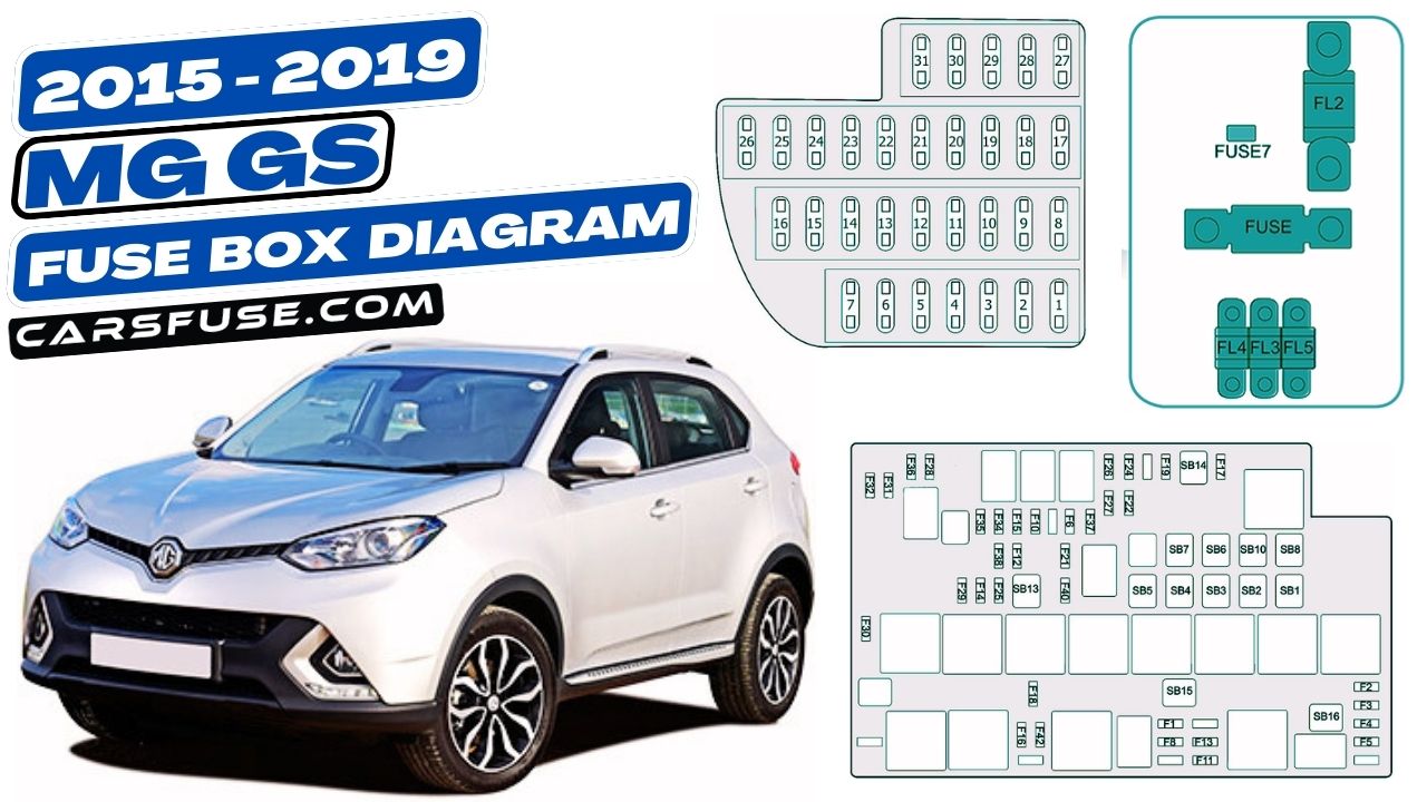
The MG GS is a mid-size SUV that was manufactured by MG Motor from 2015 to 2019. It was available with a variety of engines, including a 1.5-liter turbocharged gasoline engine and a 2.0-liter turbocharged gasoline engine. The GS was also available with a variety of transmissions, including a 6-speed manual transmission and a 6-speed automatic transmission.
This article provides fuse box diagrams for the MG GS from 2015 to 2019. The fuse box diagrams show the location of all of the fuses in the car, as well as the amperage rating of each fuse. This information can be helpful if you need to replace a fuse in your MG GS.
Fuses are important safety devices that protect your MG GS’s electrical system from damage. If a fuse blows, it means that there is too much current flowing through that circuit. This can happen due to a short circuit or a malfunctioning electrical component. When a fuse blows, it will need to be replaced.
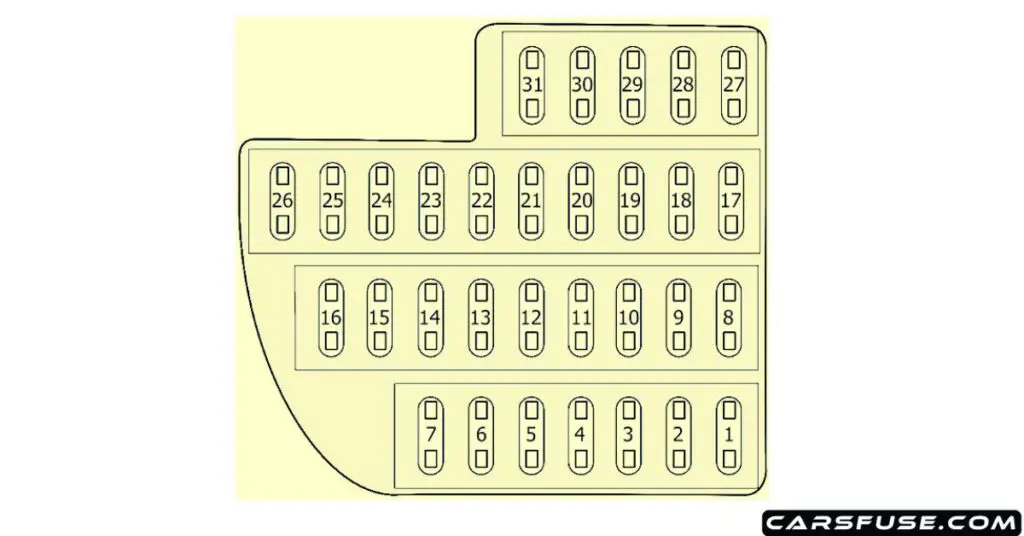
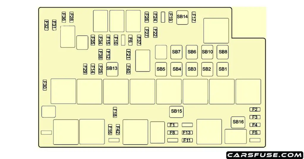
To replace a fuse in your MG GS, you will need to first locate the fuse box. The fuse boxes for the MG GS are located in the engine compartment and the passenger compartment. Once you have located the fuse box, you will need to identify the blown fuse. The blown fuse will be blackened or melted.
Table of Contents
Passenger Compartment

| Fuse Number | Fuse Amp. Rating | Protected Components |
|---|---|---|
| 1 | 15A | Rear accessories power socket |
| 2 | – | – |
| 3 | – | – |
| 4 | – | – |
| 5 | – | – |
| 6 | 5A | Radio |
| 7 | 15A | Front 12V power socket |
| 8 | 25A | TCM (7AT) |
| 9 | – | – |
| 10 | 5A | Driver door switch pack |
| 11 | 10A | Gateway |
| 12 | 5A | Parking distance control unit, rain sensor |
| 13 | 20A | Headlamp, dynamic headlamp leveling control module |
| 14 | 2A | Ignition switch |
| 15 | 5A | Immobiliser coil |
| 16 | 10A | Diagnostic socket |
| 17 | 5A | Slip control system |
| 18 | 5A | Power management DC convertor |
| 19 | 20A | Seat heater switch |
| 20 | – | – |
| 21 | 7.5A | PRND display, EPB Switch, exterior mirror adjustment, switch-stop/start system |
| 22 | 10A | Supplemental restraint system |
| 23 | – | – |
| 24 | – | – |
| 25 | 5A | Master light switch |
| 26 | – | – |
| 27 | – | – |
| 28 | 5A | Instrument pack |
| 29 | 10A | ATC controller / MTC controller |
| 30 | 5A | A/C and ICE interface |
| 31 | 15A | Radio/color radio/ NAV |
Engine Compartment

| Fuse Number | Fuse Amp. Rating | Protected Components |
|---|---|---|
| F1 | 10A | Engine control module |
| F2 | 15A | Engine control module |
| F3 | 20A | Upstream oxygen sensor, downstream oxygen sensor, clutch bottom sensor, variable camshaft timing exhaust, variable camshaft timing intake, electronic thermostat |
| F4 | 15A | Heat air flow meter, ignition coil 1~4 |
| F5 | 10A | Canister purge valve, wastegate control valve, dump valve, brake lamp switch sensor, oil control valve, neutral switch |
| F6 | 7.5A | Exterior mirror heater |
| F7 | – | – |
| F8 | 20A | Fuel pump relay |
| F9 | – | – |
| F10 | 30A | Driver door window lift motor |
| F11 | 5A | Supplemental restraint system |
| F12 | 25A | Body control module |
| F13 | 20A | Passenger power seat adjustment switch |
| F14 | 25A | Body control module |
| F15 | 30A | Front passenger door window lift switch |
| F16 | 10A | TCM (TST), engine control module, shift control module (TST) |
| F17 | 10A | Air condition compressor relay |
| F18 | 5A | Engine control module |
| F19 | 20A | Driver power seat adjustment switch |
| F20 | — | — |
| F21 | 10A | Ignition switch relay |
| F22 | 25A | Body control module |
| F23 | – | – |
| F24 | 5A | Transmission relay coil (TST) |
| F25 | 25A | Body control module |
| F26 | 30A | Rear left window lift switch |
| F27 | 30A | Rear right window lift switch |
| F28 | 20A | Horn relay |
| F29 | 25A | Front wiper relay |
| F30 | 20A | Front windscreen washer relay |
| F31 | 20A | Rear windscreen wiper relay |
| F32 | 20A | Rear windscreen washer relay |
| F33 | – | – |
| F34 | 10A | Front left headlamp |
| F35 | 10A | Front right headlamp |
| F36 | 30A | Headlamp washer relay |
| F37 | 15A | Front fog lamp relay |
| F38 | 25A | Body control module |
| F39 | – | – |
| F40 | 30A | Rear windscreen heater relay |
| F41 | – | – |
| F42 | 10A | Reverse lamp switch (6MT), body control module, instrument pack, MTC controller |
| SB1 | 30A | Main relay |
| SB2 | 60A | Cooling fan-high speed |
| SB3 | 50A | Cooling fan-middle speed |
| SB4 | 40A | KL.R power control relay |
| SB5 | 40A | Starter relay |
| SB6 | 30A | Slip control system-valve |
| SB7 | 40A | Slip control system-pump |
| SB8 | 40A | Blower relay |
| SB9 | – | – |
| SB10 | 25A | Body control module |
| SB11 | – | – |
| SB12 | – | – |
| SB13 | 40A | TCM (TST) |
| SB14 | 40A | Electrical park brake control module |
| SB15 | 40A | Power management DC convertor |
| SB16 | 40A | Cooling fan-low speed |
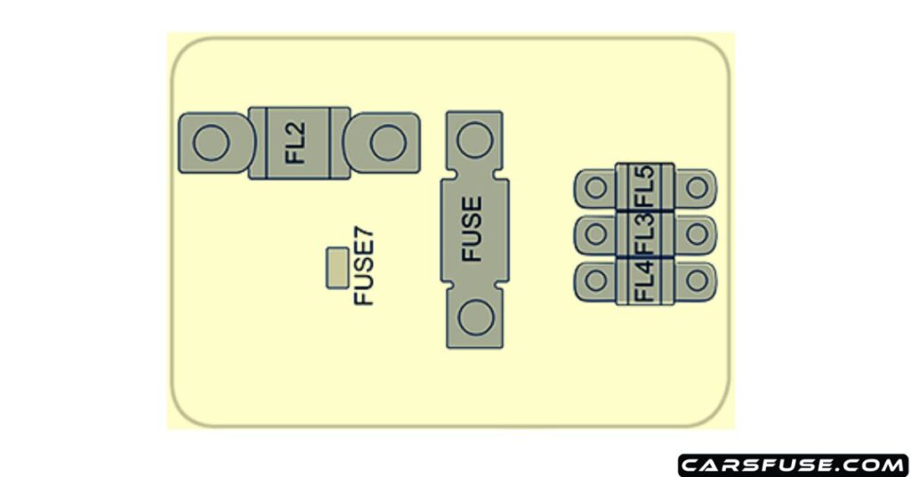
Fuses in the Battery Fuse Box

| Code | Fuse Amp. Rating | Protected Components |
|---|---|---|
| FUSE | – | – |
| FUSE7 | 5A | Power management DC convertor |
| FL2 | 200A | Alternator |
| FL3 | 60A | Electronic power assisted steering |
| FL4 | 200A | Engine compartment fuse box |
| FL5 | 50A | Passenger compartment fuse box |
Next Post: 2020-2023 MG HS PHEV/eHS Fuse Box Diagram
Tom Smith is a passionate car mechanic and automotive enthusiast, specializing in the intricate world of car fuse boxes. With years of hands-on experience under the hood, he has earned a reputation as a reliable expert in his field. As the founder and content creator of the popular blog website 'carsfuse.com,' Tom has dedicated himself to sharing his extensive knowledge of car fuse boxes and electrical systems with the world.

