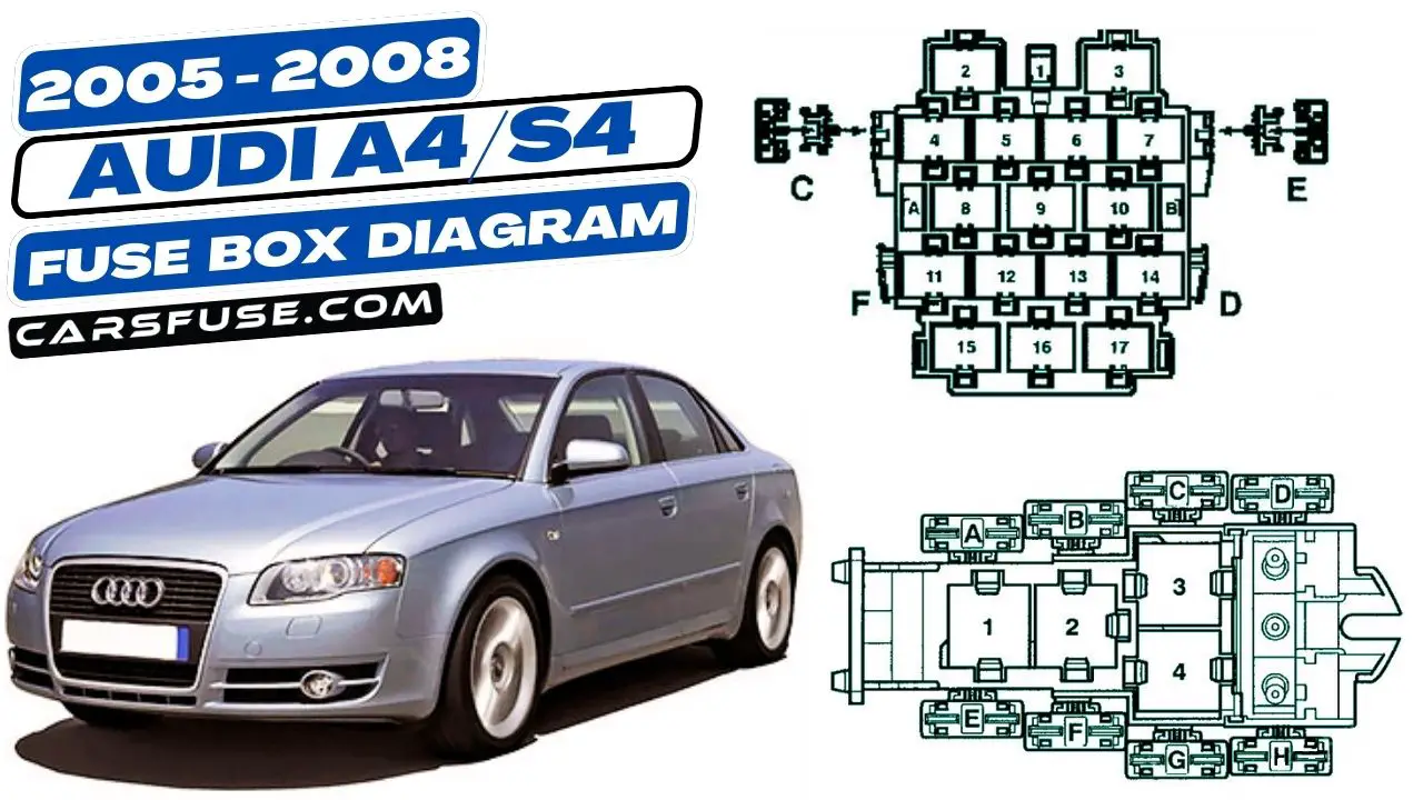
The Audi A4/S4 8E/8H is a popular luxury car that was produced from 2005 to 2008. Like all cars, it has a fuse box that houses the electrical fuses for the car’s various systems. If you are having electrical problems with your Audi A4/S4 8E/8H, it can be helpful to consult the fuse box diagram to see which fuse may be blown.
In this blog post, I will provide you with the fuse box locations and diagrams for the Audi A4/S4 8E/8H. I will also discuss how to troubleshoot electrical problems using the fuse box diagrams.
By understanding the fuse box locations and diagrams for your Audi A4/S4 8E/8H, you can troubleshoot electrical problems more easily. This can save you time and money in the long run.
Table of Contents
Instrument Panel
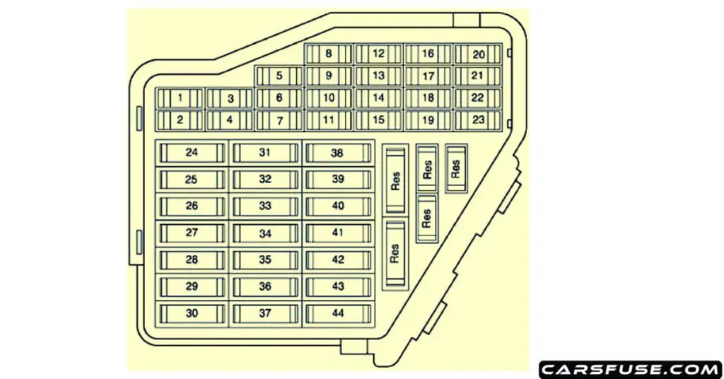
| Fuse Number | Fuse Amp. Rating | Function/Component |
|---|---|---|
| 1 | 10A | Climatronic Control Module |
| 2 | 5A | Left Footwell Light Right Footwell Light |
| 3 | 5A | Left Washer Nozzle Heater Right Washer Nozzle Heater Left Rear Footwell Light Right Rear Footwell Light |
| 4 | 5A | Coolant Fan Control (FC) Control Module Coolant Fan Control (FC) Control Module 2 |
| 5 | 10A | Rear Window Shade Switch Function Selector Switch II Tiptronic Switch Oil Level Thermal Sensor Rear Window Shade Control Module Navigation System with CD Drive Control Module Parking Aid Control Module |
| 6 | 5A | High Pressure Sensor Sensor for air quality |
| 7 | 10A | Anti-Slip Control Switch Clutch Pedal Switch Brake Pedal Switch ABS Control Module |
| 8 | 5A | Telephone Transceiver Telephone Amplifier |
| 9 | 15A | Brake Booster Relay |
| 10 | 5A | Headlamp Adjuster Headlamp Range Control Module Headlamp Range/Comering Lamp Control Module Left Headlamp Beam Adjusting Motor Right Headlamp Beam Adjusting Motor Right Dynamic Cornering Light Motor |
| 11 | 5A | Airbag Control Module Warning Lamp for airbag off, passenger side |
| 12 | 10A | 16 pin connector, black, diagnostic connector |
| 13 | 10A | Steering Column Electronic Systems Control Module |
| 14 | 10A | Brake Light Switch |
| 15 | 10A | Instrument Cluster Control Module Navigation System with CD Drive Control Module |
| 16 | 5A | Garage Door Opener Control Head Garage Door Opener Control Module |
| 17 | 10A | Rain/Light Recognition Sensor Parking Aid Control Module Tire Pressure Monitoring Control Module |
| 18 | 5A | Left Dynamic Cornering Light Motor |
| 19 | 10A | Left Lront Fog Lamp Right Front Fog Lamp |
| 20 | – | Not used |
| 21 | – | Not used |
| 22 | 15A | Drivers Door Control Module Front Passenger’s Door Control Module |
| 23 | 15A | Left Rear Door Control Module Right Rear Door Control Module |
| 24 | 20A | Comfort System Central Control Module |
| 25 | 30A | Fresh Air Blower Control Module |
| 26 | 30A | Rear Window Defogger Relay |
| 27 | 30A | Towing Recognition Control Module |
| 28 | 20A | Transfer Fuel Pump (FP) Fuel Pump (FP) Control Module |
| 29 | – | Not used |
| 30 | 20A | Power Sunroof Control Module |
| 31 | 15A | Back-Up Light Switch Mass Air Flow (MAF) Sensor Light Recognition Sensor Starting Interlock Relay Transmission Control Module (ICM) |
| 32 | 15A | Trailer Socket |
| 33 | 15A/20A | Cigarette lighter |
| 34 | 20A/30A | 12V Socket |
| 35 | 20A/30A | Socket |
| 36 | 30A | Vehicle Electrical System Control Module Rear Window Wiper Motor |
| 37 | 30A | Vehicle Electrical System Control Module Headlamp Washer Pump |
| 38 | 15A | Radar Interior Monitoring Control Module 1 Alarm Horn Comfort System Central Control Module 8 pin Connector, black, radio connector III |
| 39 | 20A | Radio Amplifier |
| 40 | 25A | High Tone Horn Low Tone Horn Horn Relay |
| 41 | 30A | Auxiliary Heater Control Module Auxiliary Heater Radio Receiver |
| 42 | 25A | ABS Control Module |
| 43 | 15A | Engine Timing Mass Air Flow (MAF) Sensor EGR Potentiometer SIMOS Control Module Power Supply Relay Engine Control Module (ECM) Engine Component Power Supply Relay EGR Vacuum Regulator Solenoid Valve |
| 44 | 30A | Climatronic Control Module |
Connector station – Right A-pillar
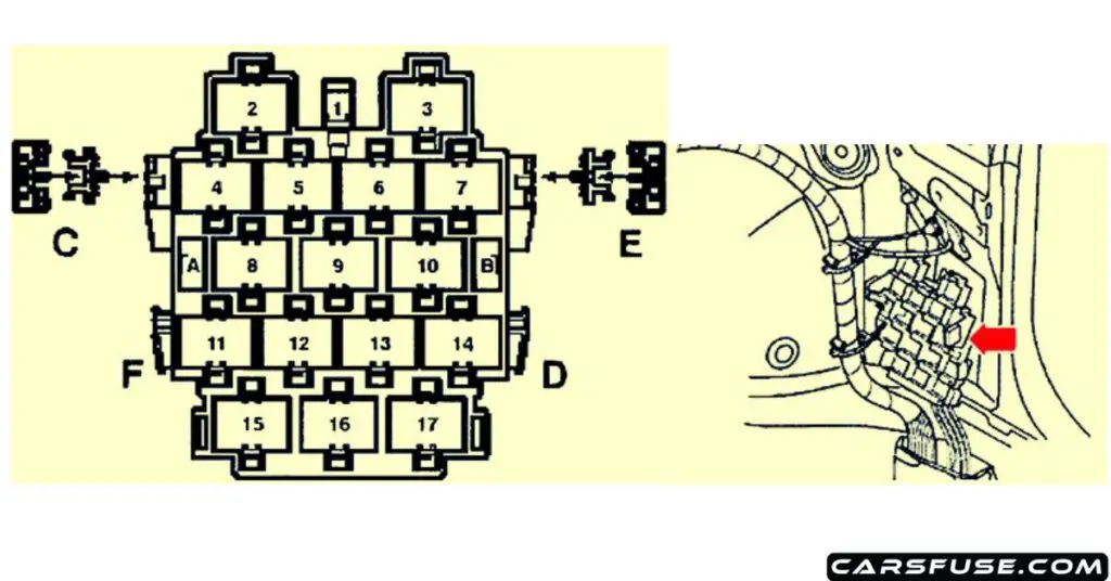
| Fuse Number | Fuse Amp. Rating | Circuit Protected |
|---|---|---|
| E | 30A | Power Seat (with manual seats with power lumbar) |
| E | 10A | Power Seat (with power seats) |
Relay Panels
Relay panel (4-position) with threaded connection
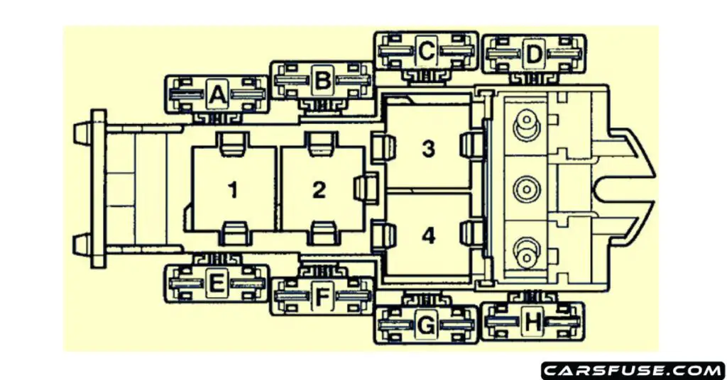
| Fuse Number | Fuse Amp. Rating | Circuit Protected |
|---|---|---|
| F | 10A/40A/60A | Fuse (Driver Fan training vehicle) (Not for Engine code BBK, BHF) Coolant Fan Fuse (Engine code BBK, BHF, BNS, BKN) |
| G | 30A/40A/60A | Radiator After run Fuse (Engine code BBK, BHF, BNS, BKN) Coolant Fan Fuse (Not for Engine code BKN, BBK, BHF) |
| H | 40A | ABS Control Module Fuse 1 |
| 3 | NG Engine Throttle Relay 1 (not applicable to USA/CDN models) | |
| 4 | NG Engine Throttle Relay 2 (not applicable to USA/CDN models) | |
| 4 | Alarm-On/Hands-free Control Module (not applicable to USA/CDN models) |
Relay panel (9-position)
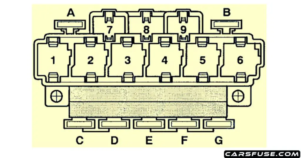
| Fuse Number | Fuse Amp. Rating | Circuit Protected |
|---|---|---|
| A | 10A | Rear Shade Circuit Breaker (Right) |
| B | 10A | Rear Shade Circuit Breaker (Left) |
| D | 30A | Power Windows Fuse 2 |
| E | 10A | Driver’s Power Seat Adjustment Circuit Breaker 2 |
| E | 10A | Driver’s Power Seat Adjustment Circuit Breaker 2 (Lumbar Support Adjustment) |
| F | 30A | Power Windows Fuse |
| G | 30A | Trailer Circuit Breaker |
| 1 | Fuel Pump (FP) Relay | |
| 2 | Servotronic Control Module | |
| 3 | Starter Relay 2 (For engine code AUK, BKH, BNS) | |
| 4 | Starter Relay 2 (For engine code AUK, BKH, BNS) Brake Booster Relay (Not applicable for engine code AUK, BKH) | |
| 5 | Rear Window Defogger Relay | |
| 6 | Load Reduction Relay | |
| 8 | Horn Relay | |
| 4 | Brake Booster Relay (Not applicable for engine code AUK, BKH) |
Next Post: 1998-2001 Audi A4/S4 Fuse Box Diagram
Tom Smith is a passionate car mechanic and automotive enthusiast, specializing in the intricate world of car fuse boxes. With years of hands-on experience under the hood, he has earned a reputation as a reliable expert in his field. As the founder and content creator of the popular blog website 'carsfuse.com,' Tom has dedicated himself to sharing his extensive knowledge of car fuse boxes and electrical systems with the world.

