In this article, we will provide you with an in-depth exploration of the 2023 Ford Expedition fuse box diagram. We’ll unravel the complexities and discover the purpose of each fuse, enabling you to navigate your electrical system with confidence and ease.
Table of Contents
Note: All information contained in this Quick Reference Guide was accurate at the time of duplication. For detailed operating and safety information, please consult your Ford Expedition Owner’s Manual.
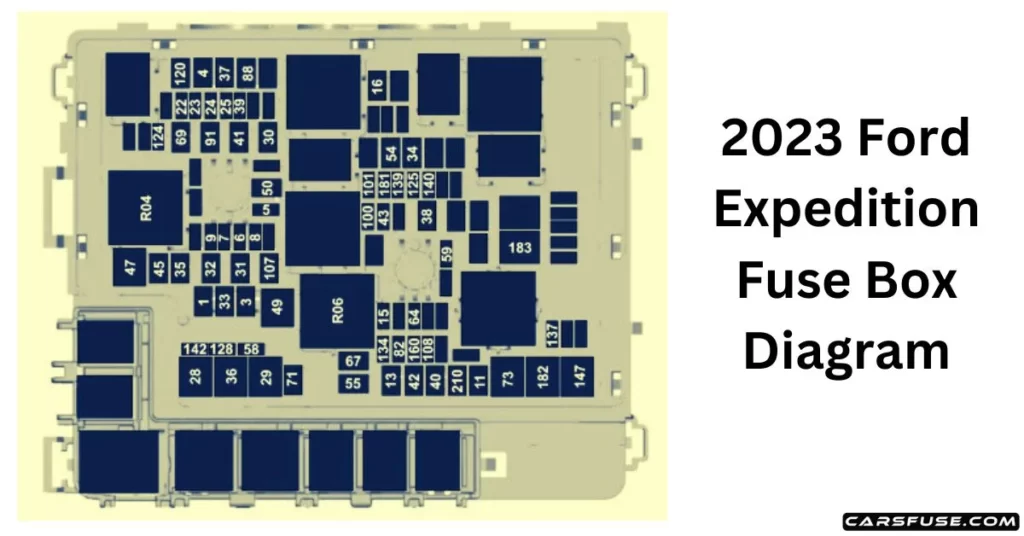
2023 Ford Expedition Fuse Box Diagram
(Underhood Fuse Box)
Note: In the event that you need to disconnect and reconnect the battery, it's important to note that certain features may require resetting. This step is necessary to restore their functionality.

The high-current fuses are coded as follows:
| Item | Rating | Protected Component |
| 1 | 30 A | Body control module 1. |
| 3 | 30 A | Body control module 2. |
| 4 | 30 A | Fuel pump. |
| 5 | 5 A | Powertrain control module relay. |
| 6 | 20 A | Vehicle power 1. |
| 7 | 25 A | Vehicle power 2. |
| 8 | 20 A | Vehicle power 3. |
| 9 | 20 A | Vehicle power 4. |
| 11 | 30 A | Starter relay. |
| 13 | 40 A | Front blower motor. |
| 15 | 20 A | Horn. |
| 16 | 20 A | Windshield washer pump. |
| 22 | 10 A | Electronic power assist steering run/start feed. |
| 23 | 10 A | Anti-lock brake system run/start feed. |
| 24 | 10 A | Powertrain control module. Transmission control module. |
| 25 | 10 A | Rearview camera. Air quality sensor run/start feed. |
| 28 | 50 A | Anti-lock brake system pump. |
| 29 | 50 A | Anti-lock brake system valves. |
| 30 | 30 A | Driver seat motors. |
| 31 | 30 A | Passenger seat motors. |
| 32 | 20 A | Powerpoint 1. |
| 33 | — | Not used. |
| 34 | 20 A | Powerpoint 3. |
| 35 | 20 A | Powerpoint 4. |
| 36 | 40 A | Inverter. |
| 37 | 30 A | Climate-controlled seats – passenger side. |
| 38 | 30 A | Climate-controlled seats – driver side. |
| 39 | 20 A | Second-row seat module. |
| 40 | 40 A | Power running boards. |
| 41 | 30 A | Powered liftgate module. |
| 42 | 30 A | Trailer brake control module. |
| 43 | 5 A | Not used (spare). |
| 45 | 20 A | Powerpoint 5. |
| 47 | 50 A | Electric fan 1. |
| 49 | 50 A | Electric fan 2. |
| 50 | 40 A | Heated rear window. |
| 54 | 40 A | Electronic limited-slip differential. |
| 55 | 30 A | Trailer tow parking lamps relay. |
| 58 | 10 A | Trailer tow backup lamps. |
| 59 | 20 A | Not used (spare). |
| 64 | 25 A | Four-wheel drive module 1. |
| 67 | 15 A | Transmission run/start. |
| 69 | 30 A | Left-hand side wiper motor. |
| 71 | 20 A | Rear window wiper relay. |
| 73 | 50 A | Power folding seat module – third row. |
| 82 | 25 A | Four-wheel drive module 2. |
| 88 | 40 A | Auxiliary blower. |
| 91 | 20 A | Trailer tow lighting module power. |
| 100 | 30 A | Left-hand headlamp. |
| 101 | 30 A | Right-hand headlamp. |
| 107 | 30 A | Trailer battery charge. |
| 108 | 20 A | Spot lamps (police). |
| 120 | 15 A | Fuel injectors. |
| 124 | 5 A | Rain sensor module. |
| 125 | 5 A | USB smart charger 1. |
| 128 | 7.5 A | Family entertainment system. |
| 134 | 20 A | Multi-contour seat relay. |
| 137 | 20 A | Advanced driver-assistance systems module. Connected camera. |
| 139 | 5 A | USB smart charger 2. |
| 140 | 5 A | USB smart charger 3. |
| 142 | 5 A | USB smart charger 5. |
| 147 | 40 A | Intercooler puller fan relay. |
| 160 | 10 A | Smart data link connector. |
| 181 | 5 A | Not used (spare). |
| 182 | 60 A | Driver door control module. |
| 183 | 60 A | Passenger door control module. |
| 210 | 30 A | Body control module start stop. |
| Relay Number | Protected Component |
| R04 | Electric fan 1 relay. |
| R06 | Electric fan 3 relay. |
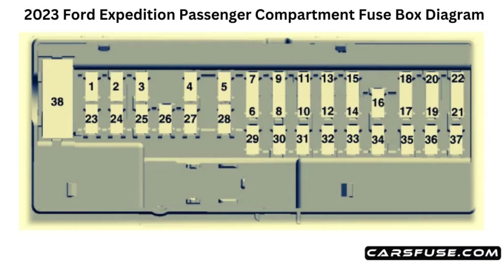
Body Control Module Fuse Box
The fuse panel in your vehicle is conveniently located on the right-hand side of the passenger footwell, concealed behind a trim panel.

| Item | Rating | Protected Component |
| 1 | — | Not used. |
| 2 | 10 A | Driver seat switch. |
| 3 | 7.5 A | Driver door unlock. |
| 4 | 20 A | Speaker amplifier. |
| 5 | — | Not used. |
| 6 | 10 A | Smart datalink connector logic. |
| 7 | 10 A | Rear audio control module. |
| 8 | 5 A | Wireless accessory charger. Hands-free liftgate module. |
| 9 | 5 A | Keypad. Combined sensor module. |
| 10 | — | Not used. |
| 11 | — | Not used. |
| 12 | 7.5 A | Instrument cluster. |
| 13 | 7.5 A | Steering column control module. Smart datalink connector logic. Climate control module. Gear shift module. |
| 14 | 15 A | Brake switch. |
| 15 | 15 A | SYNC. |
| 16 | — | Not used. |
| 17 | — | Not used. |
| 18 | 7.5 A | Gear shift module. Column shifter. |
| 19 | 5 A | Telematics control unit module. |
| 20 | 5 A | Ignition switch. |
| 21 | 5 A | In-vehicle temperature and humidity sensor. |
| 22 | 5 A | Electrochromic mirror. Second row heated seat module. |
| 23 | 30 A | Power window switch. Power mirror switch. Left-hand front door zone module. |
| 24 | 30 A | Moonroof logic. |
| 25 | 20 A | Speaker amplifier 2. |
| 26 | 30 A | Right-hand front door zone module. |
| 27 | 30 A | Left-hand rear door zone module. |
| 28 | 30 A | Right-hand rear door zone module. |
| 29 | 15 A | Adjustable pedals. |
| 30 | 5 A | Trailer tow control module. |
| 31 | 10 A | Rear climate control module. Drive mode switch module. Terrain management switch. Radio frequency transceiver module. 4×4 switch. |
| 32 | 20 A | Audio control module. |
| 33 | — | Not used. |
| 34 | 30 A | Run/start relay. |
| 35 | 5 A | Not used (spare). |
| 36 | 15 A | Image processing module A. Automated park assist module. Continuous control damping module. |
| 37 | 20 A | Heated steering wheel. |
| 38 | 30A Circuit Breaker | Left-hand rear power window. Right-hand rear power window. |

