Discover the heart of the 2022 Ford Expedition’s electrical system its fuse box. In this concise article, we gather complete information about the fuse box diagram, location, power distribution, and essential guidelines.
Unlock the secrets of maintaining and troubleshooting your Expedition’s electrical prowess.
Table of Contents
Note: All information contained in this Quick Reference Guide was accurate at the time of duplication. For detailed operating and safety information, please consult your Ford Expedition Owner’s Manual.
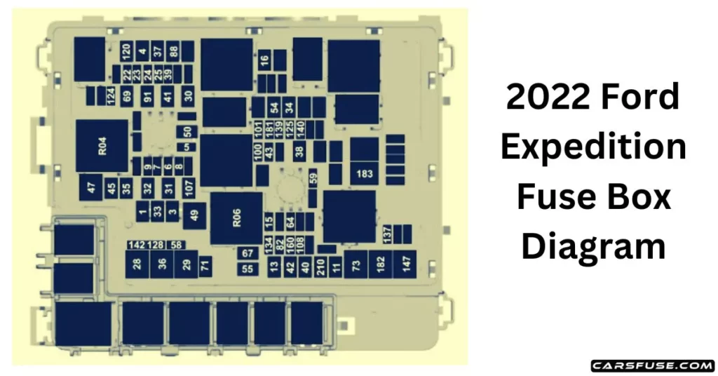
2022 Ford Expedition Fuse Box Diagram
(Under Hood Fuse Box)
Note: In the event that you need to disconnect and reconnect the battery, it's important to note that certain features may require resetting. This step is necessary to restore their functionality.
2022 FORD EXPEDITION FUSE BOX DIAGRAM
Item
Rating
Protected Component
1
30 A
Body control module 1.
3
30 A
Body control module 2.
4
30 A
Fuel pump.
5
5 A
Powertrain control module relay.
6
20 A
Vehicle power 1.
7
25 A
Vehicle power 2.
8
20 A
Vehicle power 3.
9
20 A
Vehicle power 4.
11
30 A
Starter relay.
13
40 A
Front blower motor.
15
20 A
Horn.
16
20 A
Windshield washer pump.
22
10 A
Electronic power assist steering run/start feed.
23
10 A
Anti-lock brake system run/start feed.
24
10 A
Powertrain control module. Transmission control module.
25
10 A
Rearview camera. Air quality sensor run/start feed.
28
50 A
Anti-lock brake system pump.
29
50 A
Anti-lock brake system valves.
30
30 A
Driver seat motors.
31
30 A
Passenger seat motors.
32
20 A
Powerpoint 1.
33
—
Not used.
34
20 A
Powerpoint 3.
35
20 A
Powerpoint 4.
36
40 A
Inverter.
37
30 A
Climate-controlled seats – passenger side.
38
30 A
Climate-controlled seats – driver side.
39
20 A
Second-row seat module.
40
40 A
Power running boards.
41
30 A
Powered liftgate module.
42
30 A
Trailer brake control module.
43
5 A
Not used (spare).
45
20 A
Powerpoint 5.
47
50 A
Electric fan 1.
49
50 A
Electric fan 2.
50
40 A
Heated rear window.
54
40 A
Electronic limited slip differential.
55
30 A
Trailer tow parking lamps relay.
58
10 A
Trailer tow backup lamps.
59
20 A
Not used (spare).
64
25 A
Four-wheel drive module 1.
67
15 A
Transmission run/start.
69
30 A
Left-hand side wiper motor.
71
20 A
Rear window wiper relay.
73
50 A
Power folding seat module – third row.
82
25 A
Four-wheel drive module 2.
88
40 A
Auxiliary blower.
91
20 A
Trailer tow lighting module power.
100
30 A
Left-hand headlamp.
101
30 A
Right-hand headlamp.
107
30 A
Trailer battery charge.
108
20 A
Spot lamps (police).
120
15 A
Fuel injectors.
124
5 A
Rain sensor module.
125
5 A
USB smart charger 1.
128
7.5 A
Family entertainment system.
134
20 A
Multi-contour seats relay.
137
20 A
Advanced driver-assistance systems module. Connected camera.