In this article, we will provide you with an in-depth exploration of the 2017 Ford Explorer fuse box diagram. We’ll unravel the complexities and demystify the purpose of each fuse, enabling you to navigate your electrical system with confidence and ease.
Table of Contents
2017 Ford Explorer Fuse Box Diagram (Power Distribution Box)
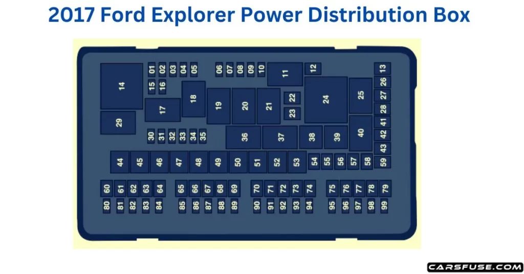
1Micro 2 fuse / 2M-case fuse / 3J-case fuse.
| Fuse or Relay Number | Fuse Rating | Protected Components |
| 1 | 20A1 | Powertrain control module power. |
| 2 | 20A1 | Engine emissions (MIL). |
| 3 | 20A1 | A/C clutch control relay coil. VACC. Active grille shutters. |
| 4 | 20A1 | Ignition coils. |
| 5 | — | Not used. |
| 6 | — | Not used. |
| 7 | — | Not used. |
| 8 | — | Not used. |
| 9 | — | Not used. |
| 10 | 15A1 | Heated mirrors. |
| 11 | — | Right hand side electronic cooling fan 3 relay. |
| 12 | 40A2 | Heated rear window. |
| 13 | — | Not used. |
| 14 | — | Powertrain control module relay. |
| 15 | 20A1 | Horn relay power. |
| 16 | 10A1 | A/C clutch relay power. |
| 17 | — | Rear heated window and heated mirrors relay. |
| 18 | — | Rear blower motor relay. |
| 19 | — | Not used. |
| 20 | — | Left hand side cooling fan relay. |
| 21 | — | Cooling fans series/parallel relay. |
| 22 | 25A2 | Electronic fan relay 2. |
| 23 | — | Not used. |
| 24 | — | Not used. |
| 25 | — | Not used. |
| 26 | 30A2 | Anti-lock brake system valves. |
| 27 | 30A2 | Trailer tow battery charge relay power. |
| 28 | — | Not used. |
| 29 | — | Run/start relay. |
| 30 | — | Not used. |
| 31 | 10A1 | Electric power-assisted steering. |
| 32 | 10A1 | Anti-lock brake system module. |
| 33 | 10A1 | Powertrain control module (ISPR). |
| 34 | 10A1 | Blind spot information system. Adaptive cruise control. Front view camera. Rear camera. |
| 35 | — | Not used. |
| 36 | — | Blower motor relay. |
| 37 | — | Trailer tow battery charge relay. |
| 38 | — | A/C compressor clutch relay. |
| 39 | — | Horn relay. |
| 40 | — | Not used. |
| 41 | 40A2 | Rear blower motor. |
| 42 | — | Not used. |
| 43 | 40A2 | Front blower motor. |
| 44 | 50A3 | Voltage quality module bus. |
| 45 | 40A3 | Electronic fan relay 1. |
| 46 | 30A3 | Trailer tow brake controller. |
| 47 | — | Not used. |
| 48 | 50A3 | Body control module RP1 bus. |
| 49 | — | Not used. |
| 50 | 50A3 | Body control module RP2 bus. |
| 51 | 50A3 | Electronic fan relay 3. |
| 52 | 60A3 | Anti-lock brake system pump. |
| 53 | — | Not used. |
| 54 | — | Not used. |
| 55 | — | Not used. |
| 56 | 40A2 | Power inverter. |
| 57 | — | Not used. |
| 58 | — | Not used. |
| 59 | — | Not used. |
| 60 | 20A2 | Power point (front console bin). |
| 61 | — | Not used. |
| 62 | 20A2 | Power point (instrument panel). |
| 63 | 30A2 | Fuel pump. |
| 64 | — | Not used. |
| 65 | 20A2 | Power point (2nd row) (without USB charger). |
| 66 | — | Not used. |
| 67 | 20A2 | Power point (cargo area). |
| 68 | — | Not used. |
| 69 | 30A2 | Power liftgate. |
| 70 | 15A2 | Trailer tow left-hand and right-hand stop and direction indicator lamps. |
| 71 | — | Not used. |
| 72 | 30A2 | Heated/cooled seats. |
| 73 | 30A2 | Driver seat module. Driver seat power. |
| 74 | 30A2 | Passenger seat power. |
| 75 | 30A2 | Front wiper motor. |
| 76 | — | Not used. |
| 77 | — | Not used. |
| 78 | 30A2 | 3rd row power folding seat module relay. |
| 79 | 30A2 | Starter relay. |
| 80 | — | Not used. |
| 81 | 10A1 | Trailer tow back-up lamp relay. |
| 82 | — | Not used. |
| 83 | 10A1 | Brake on/off switch. |
| 84 | — | Not used. |
| 85 | 5A1 | 2nd row USB charger (if equipped). |
| 86 | — | Not used. |
| 87 | — | Not used. |
| 88 | — | Not used. |
| 89 | — | Not used. |
| 90 | — | Not used. |
| 91 | — | Not used. |
| 92 | 15A1 | Multi-contour seat module relay. |
| 93 | 10A1 | Alternator sense. |
| 94 | 15A1 | Rear washer relay. |
| 95 | 15A1 | Rear wiper relay. |
| 96 | 10A1 | Powertrain control module relay coil power. |
| 97 | 5A1 | Rain sensor. |
| 98 | 20A1 | 2nd row seat motors. |
| 99 | 20A1 | Trailer tow parking lamp relay. |
2017 Ford Explorer Fuse Box Diagram (Passenger Compartment Fuse Panel)
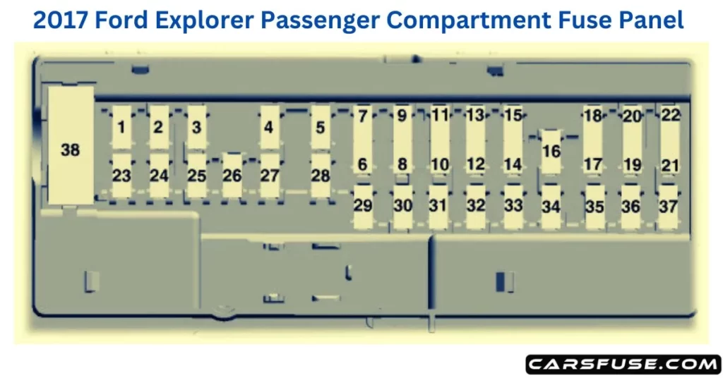
1Micro 2 fuse / 2Micro 3 fuse / 3Circuit breaker
| Fuse or relay number | Fuse Rating | Protected Components |
| 1 | 10A1 | Demand lamps. Battery saver. |
| 2 | 7.5A1 | Memory seat switch (lumbar power). |
| 3 | 20A1 | Driver unlock relay. |
| 4 | 5A1 | Aftermarket electronic brake controller. |
| 5 | 20A1 | Rear heated seat module. |
| 6 | — | Not used. |
| 7 | — | Not used. |
| 8 | — | Not used. |
| 9 | — | Not used. |
| 10 | 5A2 | Securicode™ keyless entry keypad. Hands free liftgate. |
| 11 | 5A2 | Rear climate control module. |
| 12 | 7.5A2 | Front climate control module. |
| 13 | 7.5A2 | Instrument cluster. Smart data link. Steering column control module. |
| 14 | 10A2 | Extended power module. |
| 15 | 10A2 | Smart datalink connector power. Heads up display. |
| 16 | — | Not used. |
| 17 | 5A2 | Electronic finish panel. |
| 18 | 5A2 | Push button start switch. Ignition switch. Key inhibit. |
| 19 | 7.5A2 | Transmission control switch. |
| 20 | — | Not used. |
| 21 | 5A2 | Terrain management switch. Heads up display. Humidity sensor. |
| 22 | 5A2 | Occupant classification sensor. |
| 23 | 10A1 | Delayed accessory power. Power windows. Moonroof. Folding mirror relay. DC inverter. Window/moonroof switch illumination. |
| 24 | 20A1 | Central lock relay. |
| 25 | 30A1 | Left-hand front smart window motor. Door zone module. |
| 26 | 30A1 | Right-hand front smart window motor. Door zone module. |
| 27 | 30A1 | Moonroof. |
| 28 | 20A1 | Sony amplifier – 10 channel. |
| 29 | 30A1 | Sony amplifier – 14 channel. |
| 30 | — | Not used. |
| 31 | — | Not used. |
| 32 | 10A1 | SYNC. GPS module. Display. Radio frequency receiver. |
| 33 | 20A1 | Radio. |
| 34 | 30A1 | Run/start relay. |
| 35 | 5A1 | Restraints control module. Extended power module. |
| 36 | 15A1 | Lane departure warning module. Auto high beam. EC mirrors. Rear heated seats. |
| 37 | 20A1 | Heated steering wheel. |
| 38 | 30A 3 | Left-hand front window motor. Rear power window motors. |
When a car fuse blows, it cuts off the electric circuit and protects electrical components from further damage. To explore safety tips, and guidelines please click on the link "What happens when a car fuse blows?" for more details.
Tom Smith is a passionate car mechanic and automotive enthusiast, specializing in the intricate world of car fuse boxes. With years of hands-on experience under the hood, he has earned a reputation as a reliable expert in his field. As the founder and content creator of the popular blog website 'carsfuse.com,' Tom has dedicated himself to sharing his extensive knowledge of car fuse boxes and electrical systems with the world.
