In this article, we will provide a comprehensive guide to the 2015 Ford Explorer fuse box diagram, enabling owners to identify the correct fuses. Explaining the functions of each fuse, to make easier for you to understand your vehicle electrical system with confidence and ease.
Table of Contents
Important: Always disconnect the battery before servicing high-current fuses. To reduce the risk of electrical shock, always replace the cover with the power distribution box before reconnecting the battery or refilling fluid reservoirs. Always replace a fuse with one that has the specified amperage rating. Using a fuse with a higher amperage rating can cause severe wire damage and could start a fire.
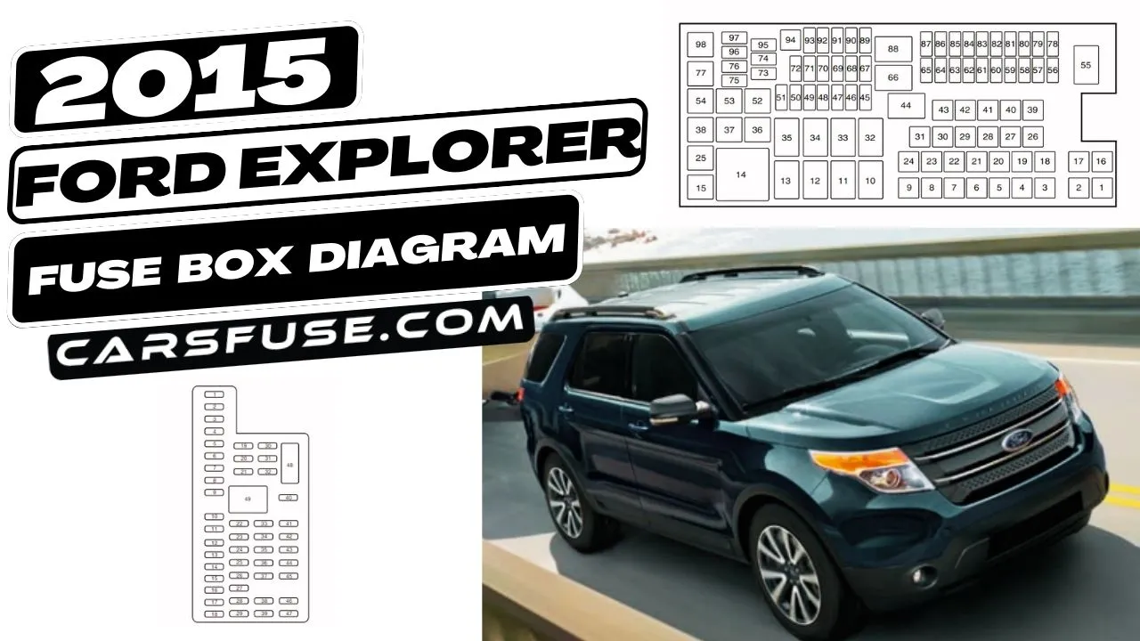
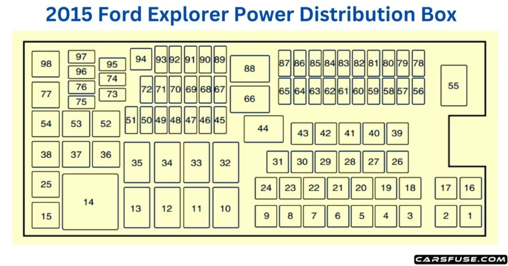
2015 Ford Explorer Fuse Box Diagram (Power Distribution Box)
Note: In the event that you need to disconnect and reconnect the battery, it's important to note that certain features may require resetting. This step is necessary to restore their functionality.

*Mini Fuses / **Cartridge Fuses
| Fuse or relay number | Fuse amp rating | Protected components |
| 1 | — | Not used |
| 2 | — | Not used |
| 3 | 30A** | Trailer brake control module |
| 4 | 30A** | Wipers, Front washer |
| 5 | 50A** | Anti-lock brake system pump |
| 6 | — | Not used |
| 7 | 30A** | Power liftgate |
| 8 | 20A** | Moonroof |
| 9 | 20A** | Power point #2 (console rear) |
| 10 | — | 3rd-row rear seat release relay |
| 11 | — | Rear window defroster relay |
| 12 | — | Trailer tow battery charge relay |
| 13 | — | Starter motor relay |
| 14 | — | Engine cooling fan #2 high-speed relay |
| 15 | — | Fuel pump relay |
| 16 | — | Not used |
| 17 | 40A** | 110-volt AC powerpoint |
| 18 | 40A** | Front blower motor |
| 19 | 30A** | Starter motor |
| 20 | 20A** | Power point #1, cigar lighter |
| 21 | 20A** | Power point #3 (cargo area) |
| 22 | 30A** | Third-row seat module |
| 23 | 30A** | Driver power seat, Memory module |
| 24 | 30A** | Trailer tow battery charge |
| 25 | — | Not used |
| 26 | 40A** | Rear window defroster, Heated mirrors |
| 27 | 20A** | Powerpoint (console) |
| 28 | 30A** | Climate controlled seats |
| 29 | 40A** | Engine cooling fan #1 high-speed power, Engine cooling fan #1 and#2 low-speed primary fuse |
| 30 | 40A** | Engine cooling fan #2 high-speed fuse |
| 31 | 25A** | Engine cooling fan #1 and #2 low speed secondary fuse |
| 32 | — | Auxiliary blower motor relay |
| 33 | — | Engine cooling fan #1 and #2 low speed relay #2 |
| 34 | — | Blower motor relay |
| 35 | — | Engine cooling fan #1 high speed relay, Engine cooling fan #1 and#2 low speed relay #1 |
| 36 | — | Not used |
| 37 | — | Trailer tow right stop/turn lamps relay |
| 38 | — | Trailer tow backup relay |
| 39 | 40A** | Auxiliary blower motor |
| 40 | — | Not used |
| 41 | 30A** | Second-row heated seats |
| 42 | 30A** | Passenger seat |
| 43 | 40A** | Anti-lock brake system valves |
| 44 | — | Rear washer relay |
| 45 | 5A* | Rain sensor |
| 46 | — | Not used |
| 47 | — | Not used |
| 48 | — | Not used |
| 49 | — | Not used |
| 50 | 15A* | Heated mirrors |
| 51 | — | Not used |
| 52 | — | Not used |
| 53 | — | Trailer tow left stop/turn lamps relay |
| 54 | — | Not used |
| 55 | — | Wiper relay |
| 56 | 15A* | Transmission control module |
| 57 | 20A* | Left high-intensity discharge headlamps |
| 58 | 10A* | Alternator sensor |
| 59 | 10A* | Brake on/off switch |
| 60 | 10A* | Trailer tow backup lamps |
| 61 | 20A* | Second-row seat release |
| 62 | 10A* | Air conditioning clutch |
| 63 | 15A* | Trailer tow stop/turn lamps |
| 64 | 15A* | Rear wipers |
| 65 | 30A* | Fuel pump |
| 66 | — | Powertrain control module relay |
| 67 | 20A* | Vehicle power #2 (emission-related powertrain components) |
| 68 | 20A* | Vehicle power #4 (ignition coils) |
| 69 | 20A* | Vehicle power #1 (powertrain control module) |
| 70 | 10A* | Vehicle power #3 (coil), All-wheel drive module, Air conditioning variable compressor control |
| 71 | — | Not used |
| 72 | — | Not used |
| 73 | — | Not used |
| 74 | — | Not used |
| 75 | — | Not used |
| 76 | — | Not used |
| 77 | — | Trailer tow park lamps relay |
| 78 | 20A* | Right high-intensity discharge headlamps |
| 79 | 5A* | Adaptive cruise control |
| 80 | — | Not used |
| 81 | — | Not used |
| 82 | 15A* | Rear washer |
| 83 | — | Not used |
| 84 | 20A* | Trailer tow park lamps |
| 85 | — | Not used |
| 86 | 7.5A* | Powertrain control module keep-alive power, Powertrain control module relay, Canister vent solenoid |
| 87 | 5A* | Run/start relay coil |
| 88 | — | Run/start relay |
| 89 | 5A* | Front blower relay coil, Electronic power assist steering module |
| 90 | 10A* | Powertrain control module, Transmission control module, Engine control module (2.0L engine) |
| 91 | 10A* | Adaptive cruise control |
| 92 | 10A* | Anti-lock brake system module, Plant EVAC, and fill |
| 93 | 5A* | Rear blower motor, Rear defroster, Trailer tow battery charge relays |
| 94 | 30A** | Passenger compartment fuse panel run/start |
| 95 | — | Not used |
| 96 | — | Not used |
| 97 | — | Not used |
| 98 | — | Air conditioning clutch relay |
2015 Ford Explorer Fuse Box Diagram (Passenger Compartment Fuse Panel)

| Fuse or relay number | Fuse amp rating | Protected components |
| 1 | 30A | One-touch up and down driver front window |
| 2 | 15A | Not used (spare) |
| 3 | 30A | One-touch up and down passenger front window |
| 4 | 10A | Interior demand lamps (overhead console, second row, cargo), Glove box lamp, Second and third-row seat release, Visor lamps |
| 5 | 20A | Amplifier |
| 6 | 5A | Not used (spare) |
| 7 | 7.5A | Memory seat module logic feed |
| 8 | 10A | Not used (spare) |
| 9 | 10A | 4-inch radio display, Power liftgate logic, Electronic finish panel, SYNC |
| 10 | 10A | Run/accessory relay (wipers, rear washer), Rain sensor |
| 11 | 10A | Instrument cluster, Heads-up display |
| 12 | 15A | Interior courtesy lamps (overhead console, Second row, cargo), Puddle lamps, Console bin LED, Backlighting |
| 13 | 15A | Right turn lamps, Right trailer tow turn/stop lamps |
| 14 | 15A | Left turn lamps, Left trailer tow turn/stop lamps |
| 15 | 15A | Reverse lamps, Stop lamps, High-mounted stop lamp |
| 16 | 10A | Low beam headlamps (right) |
| 17 | 10A | Low beam headlamps (left) |
| 18 | 10A | Keypad illumination, Brake shift interlock, Start button run indicator, Passive anti-theft system, Powertrain control module wake-up, Rear seat power enable |
| 19 | 20A | Memory seat power |
| 20 | 20A | Locks |
| 21 | 10A | Intelligent access, Keypad |
| 22 | 20A | Horn relay |
| 23 | 15A | Steering wheel control module, Intelligent access, Headlamp switch |
| 24 | 15A | Datalink connector, Steering wheel control module |
| 25 | 15A | Liftgate release |
| 26 | 5A | Radio frequency module |
| 27 | 20A | Intelligent access module |
| 28 | 15A | Ignition switch, Push-button start switch |
| 29 | 20A | Radio, Global positioning system module |
| 30 | 15A | Front park lamps |
| 31 | 5A | Trailer tow brake controller |
| 32 | 15A | Keypad illumination, Brake shift interlock, Start button run indicator, Passive anti-theft system, Powertrain control module wake-up, and Rear seat power enable |
| 33 | 10A | Occupant classification sensor |
| 34 | 10A | Blind spot monitor, Rearview camera, Reverse sensing system, Lane departure warning module, Second row heated seats module |
| 35 | 5A | Heads-up display, Climate control humidity sensor, Terrain management system, Hill descent switch, Headlamp switch ignition sensor |
| 36 | 10A | Heated steering wheel |
| 37 | 10A | Restraints control module |
| 38 | 10A | Auto-dimming rearview mirror, Moonroof |
| 39 | 15A | High beam headlamp shutters |
| 40 | 10A | Rear park lamps, License plate lamps, Trailer tow park lamps |
| 41 | 7.5A | Overdrive cancel, Tow/haul |
| 42 | 5A | Not used (spare) |
| 43 | 10A | Not used (spare) |
| 44 | 10A | Not used (spare) |
| 45 | 5A | Not used (spare) |
| 46 | 10A | Climate control module |
| 47 | 15A | Fog lamps, left and right turn signal mirror feed |
| 48 | 30A CircuitBreaker | Rear power windows, Passenger power window, One-touch down (driver side only), Driver window switch |
| 49 | Delayed accessory relay | Body control module |
Enhance your understanding of car electrical systems and address fuse-related challenges with confidence. Please do check on the link "What is car fuse box diagram?" will give a straightforward explanation of a fuse box diagram that displays how a fuse box is set up.
Tom Smith is a passionate car mechanic and automotive enthusiast, specializing in the intricate world of car fuse boxes. With years of hands-on experience under the hood, he has earned a reputation as a reliable expert in his field. As the founder and content creator of the popular blog website 'carsfuse.com,' Tom has dedicated himself to sharing his extensive knowledge of car fuse boxes and electrical systems with the world.
