
Table of Contents
Note: All information contained in this Quick Reference Guide was accurate at the time of duplication. For detailed operating and safety information, please consult your Owner’s Manual.
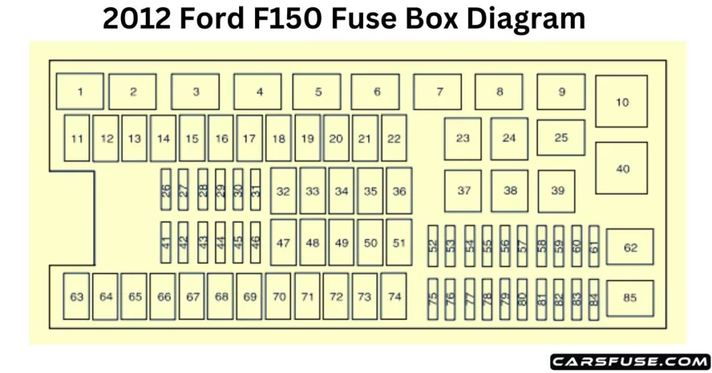
2012 Ford F150 Power Distribution Box Diagram
The power distribution box is located in the engine compartment. It has high-current fuses that protect your vehicle’s main electrical systems from overloads. If you disconnect and reconnect the battery, you will need to reset some features. The high-current fuses are coded as follows:
Note: In the event that you need to disconnect and reconnect the battery, it's important to note that certain features may require resetting. This step is necessary to restore their functionality.
*Mini fuse/ **Cartridge fuse
Spare fuse amperage may vary.
| Fuse/Relay Location | Fuse AmpRating | Protected Circuits |
| 1 | — | Powertrain control module (PCM) relay (3.7L, 5.0L, and 6.2L engines) |
| 2 | — | Starter relay |
| 3 | — | Blower motor relay |
| 4 | — | Rear window defroster relay |
| 5 | — | Electric fan relay (high speed) |
| 6 | — | Trailer tow (TT) park lamp relay |
| 7 | — | Run/start relay |
| 8 | — | Fuel pump relay |
| 9 | — | TT Battery charger relay |
| 10 | — | PCM relay (3.5L engine) |
| 11 | 30A** | Power running board motors |
| 12 | 40A** | Electric fan |
| 50A** | Electric fan (6.2L with max trailer tow, SVT Raptor) | |
| 13 | 30A** | Starter relay power |
| 14 | 30A** | Passenger power seat |
| 15 | 40A** | Electric fan |
| 50A** | Electric fan (6.2L with max trailer tow, SVT Raptor) | |
| 16 | — | Not used |
| 17 | 30A** | Trailer brake control |
| 18 | 30A** | Upfitter 1 (SVT Raptor) |
| 19 | 30A** | Upfitter 2 (SVT Raptor) |
| 20 | 20A** | 4×4 module (electronic shift) |
| 21 | 30A** | TT battery charge relay power |
| 22 | 20A** | Cigar lighter |
| 23 | — | A/C clutch relay |
| 24 | — | Not used |
| 25 | — | Vacuum pump relay (3.5L engine) |
| 26 | 10A* | PCM – keep alive power, PCM relay coil, canister vent solenoid (3.7L,5.0L and 6.2L engines) |
| 27 | 20A* | Fuel pump relay power |
| 28 | 10A* | Upfitter 4 (SVT Raptor) |
| 29 | 10A* | 4×4 IWE solenoid |
| 30 | 10A* | A/C clutch |
| 31 | 15A* | Run/start relay power |
| 32 | 40A** | Rear window defroster relay power, Heated mirror relay power |
| 33 | 40A** | 110V AC PowerPoint |
| 34 | 40A** | PCM relay power (3.7L, 5.0L and6.2L engines) |
| 50A** | PCM relay power (3.5L engine) | |
| 35 | — | Not used |
| 36 | 30A** | Roll stability control(RSC)/Anti-lock brake system(ABS) |
| 37 | — | TT left stop/turn relay |
| 38 | — | TT right stop/turn relay |
| 39 | — | TT backup lamps relay |
| 40 | — | Electric fan relay |
| 41 | 15A* | Front camera washer (SVT Raptor) |
| 42 | 5A* | Run/start coil |
| 43 | 15A* | TT backup lamp relay power |
| 44 | 15A* | Upfitter 3 (SVT Raptor) |
| 45 | 10A* | Alternator sensor (non-6.2L engines) |
| 46 | 10A* | Brake on/off (BOO) switch |
| 47 | 60A** | RSC/ABS module |
| 48 | 20A** | Moon roof |
| 49 | 30A** | Wipers |
| 50 | — | Not used |
| 51 | 40A** | Blower motor relay power |
| 52 | 5A* | Run/start – Electronic power assist steering, Blower relay coil |
| 53 | 5A* | Run/start – PCM |
| 54 | 5A* | Run/start – 4×4 module, Backup lamps, RSC/ABS, TT battery charge relay coil, Rear window defroster relay coil, Front camera washer relay coil (SVT Raptor) |
| 55 | — | Not used |
| 56 | 15A* | Heated mirrors |
| 57 | — | Not used |
| 58 | — | Not used |
| 59 | — | Not used |
| 60 | — | Not used |
| 61 | — | Not used |
| 62 | — | Wiper motor relay |
| 63 | 25A** | Electric fan |
| 64 | 40A** | Vacuum pump relay power (3.5L engine) |
| 65 | 20A** | Auxiliary power point (instrument panel) |
| 66 | 20A** | Auxiliary power point (inside center console) |
| 67 | 20A** | TT park lamps relay power |
| 68 | 25A** | 4×4 module |
| 69 | 30A** | Passenger heated/cooled seats |
| 70 | — | Not used |
| 71 | 20A** | Heated rear seats |
| 72 | 20A** | Auxiliary power point (Rear) |
| 73 | 20A** | TT stop/turn lamps relay power |
| 74 | 30A** | Driver power seat/memory module |
| 75 | 15A* | PCM – voltage power 1 (3.7L, 5.0L,6.2L engines PCM module) |
| 25A* | PCM – voltage power 1 (3.5L engine PCM module) | |
| 76 | 20A* | PCM – Voltage power 2 (General powertrain components, Mass air flow/Intake air temp sensor) (3.7L,5.0L, 6.2L engines) |
| 20A* | PCM – Voltage power 2 (General powertrain components, Canister vent solenoid) (3.5L engine) | |
| 77 | 10A* | PCM – Voltage power 3 (Emission-related powertrain components, Electric fan relays coil) |
| 78 | 15A* | PCM – Voltage power 4 – Ignition coils (3.5L, 3.7L, 5.0L engines) |
| 20A* | PCM – Voltage power 4 – Ignition coils (6.2L engine) | |
| 79 | 5A* | Rain sensor |
| 80 | — | Not used |
| 81 | — | Not used |
| 82 | — | Not used |
| 83 | — | Not used |
| 84 | — | Not used |
| 85 | — | Electric fan relay (low speed) |
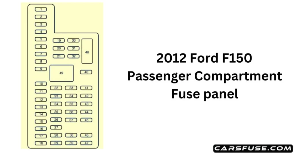
2012 Ford F150 Passenger Compartment Fuse Panel
The fuse panel is on the right-hand side of the passenger footwell behind a trim panel. To remove the fuse panel cover, press the tabs on both sides of the cover, and then pull it off. To reinstall the fuse panel cover, place the top part of the cover on the fuse panel and push the bottom part until it latches. Gently pull on the cover to make sure it has latched properly.
| Fuse/RelayLocation | Fuse AmpRating | Protected Circuits |
| 1 | 30A | Driver-side front window |
| 2 | 15A | SYNC |
| 3 | 30A | Passenger side front window |
| 4 | 10A | Interior lamps |
| 5 | 20A | Memory module |
| 6 | 5A | Not used (spare) |
| 7 | 7.5A | Power mirror switch, Memory seat module |
| 8 | 10A | Not used (spare) |
| 9 | 10A | Radio display, GPS module, Navigation display |
| 10 | 10A | Run/accessory relay |
| 11 | 10A | Instrument cluster |
| 12 | 15A | Interior lighting, Puddle lamps, Backlighting, Cargo lamp |
| 13 | 15A | Right turn signals/stop lamps |
| 14 | 15A | Left turn signals/stop lamps |
| 15 | 15A | Reverse lights, High-mounted stop lamp |
| 16 | 10A | Right low-beam headlamp |
| 17 | 10A | Left low-beam headlamp |
| 18 | 10A | Brake-shift interlock, Keypad illumination, PCM wakeup, PATS |
| 19 | 20A | Audio amplifier |
| 20 | 20A | Power door locks |
| 21 | 10A | Ambient lighting |
| 22 | 20A | Horn |
| 23 | 15A | Steering wheel control module |
| 24 | 15A | Datalink connector, Steering wheel control module |
| 25 | 15A | Not used (spare) |
| 26 | 5A | Radio frequency module |
| 27 | 20A | Not used (spare) |
| 28 | 15A | Ignition switch |
| 29 | 20A | Radio/Navigation |
| 30 | 15A | Front parking lamps |
| 31 | 5A | BOO – IP, BOO – Engine |
| 32 | 15A | Delay/accessory – moon roof, power windows, locks, Automatic dimming mirror/Compass |
| 33 | 10A | Heated seats |
| 34 | 10A | Reverse sensing system, 4×4 switch, Rear video, Off-road indicator (SVT Raptor) |
| 35 | 5A | Hill descent switch (SVT Raptor) |
| 36 | 10A | Restraint control module, Occupant classification system module |
| 37 | 10A | Trailer brake control |
| 38 | 10A | Delayed Accessory – 110V power point, Radio (AM/FM) |
| 39 | 15A | High beam headlamps |
| 40 | 10A | Rear park lamps |
| 41 | 7.5A | Passenger airbag deactivation indicator, Upfitter switch (SVTRaptor) |
| 42 | 5A | Overdrive cancel switch |
| 43 | 10A | Not used (spare) |
| 44 | 10A | Not used (spare) |
| 45 | 5A | Not used (spare) |
| 46 | 10A | Climate controls module |
| 47 | 15A | Fog lamps, Exterior mirror turn signals |
| 48 | 30A CircuitBreaker | Power rear windows, Power sliding back window |
| 49 | Relay | Delayed accessory |
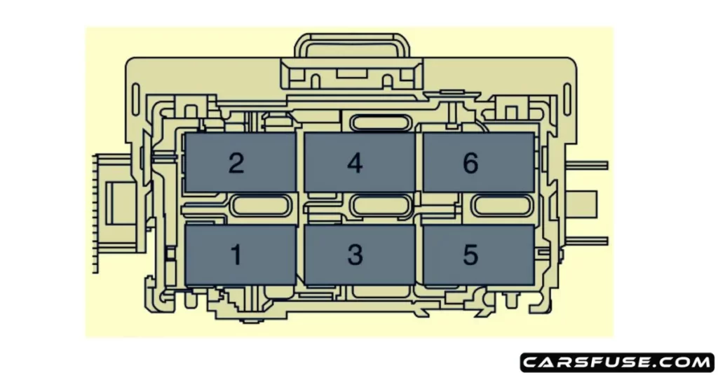
2012 Ford F150 Auxiliary relay box (SVT Raptor only)
The relay box, a clever sanctuary for electrical relays, is tucked away in the engine compartment’s left back corner. It takes on a significant role in monitoring and directing electrical activities in your car, guarding it like a sentinel. This well-placed relay box acts as a focal point, coordinating the supply of energy to multiple components.
| Fuse/Relay location | Fuse amp rating | Description |
| 1 | — | Upfitter 1 relay |
| 2 | — | Upfitter 2 relay |
| 3 | — | Upfitter 3 relay |
| 4 | — | Upfitter 4 relay |
| 5 | — | Front camera washer relay |
| 6 | — | Not used |
2012 Ford F150 Standard fuse amperage rating and color
| Fuse rating | Mini fuses | Standard fuses | Maxi fuses | Cartridge maxi fuses | Fuse link cartridge |
| 2A | Grey | Grey | — | — | — |
| 3A | Violet | Violet | — | — | — |
| 4A | Pink | Pink | — | — | — |
| 5A | Tan | Tan | — | — | — |
| 7.5A | Brown | Brown | — | — | — |
| 10A | Red | Red | — | — | — |
| 15A | Blue | Blue | — | — | — |
| 20A | Yellow | Yellow | Yellow | Blue | Blue |
| 25A | Natural | Natural | — | Natural | Natural |
| 30A | Green | Green | Green | Pink | Pink |
| 40A | — | — | Orange | Green | Green |
| 50A | — | — | Red | Red | Red |
| 60A | — | — | Blue | Yellow | Yellow |
| 70A | — | — | Tan | — | Brown |
| 80A | — | — | Natural | Black | Black |
Tom Smith is a passionate car mechanic and automotive enthusiast, specializing in the intricate world of car fuse boxes. With years of hands-on experience under the hood, he has earned a reputation as a reliable expert in his field. As the founder and content creator of the popular blog website 'carsfuse.com,' Tom has dedicated himself to sharing his extensive knowledge of car fuse boxes and electrical systems with the world.
