
Understanding the fuse box diagram can help you identify and troubleshoot electrical issues more effectively. In this blog post, we will provide you with a clear and easy-to-understand 2007 Ford F450 fuse box diagram, making it easier for you to locate and replace fuses when necessary.
So let’s dive in and explore the fuse box diagram of this powerful truck!
Table of Contents
Standard fuse amperage rating and color
| COLOR | |||||
| Fuse rating | Mini fuses | Standard fuses | Maxi fuses | Cartridge maxi fuses | Fuse link cartridge |
| 2A | Grey | Grey | — | — | — |
| 3A | Violet | Violet | — | — | — |
| 4A | Pink | Pink | — | — | — |
| 5A | Tan | Tan | — | — | — |
| 7.5A | Brown | Brown | — | — | — |
| 10A | Red | Red | — | — | — |
| 15A | Blue | Blue | — | — | — |
| 20A | Yellow | Yellow | Yellow | Blue | Blue |
| 25A | Natural | Natural | — | — | — |
| 30A | Green | Green | Green | Pink | Pink |
| 40A | — | — | Orange | Green | Green |
| 50A | — | — | Red | Red | Red |
| 60A | — | — | Blue | — | Yellow |
| 70A | — | — | Tan | — | Brown |
| 80A | — | — | Natural | — | Black |
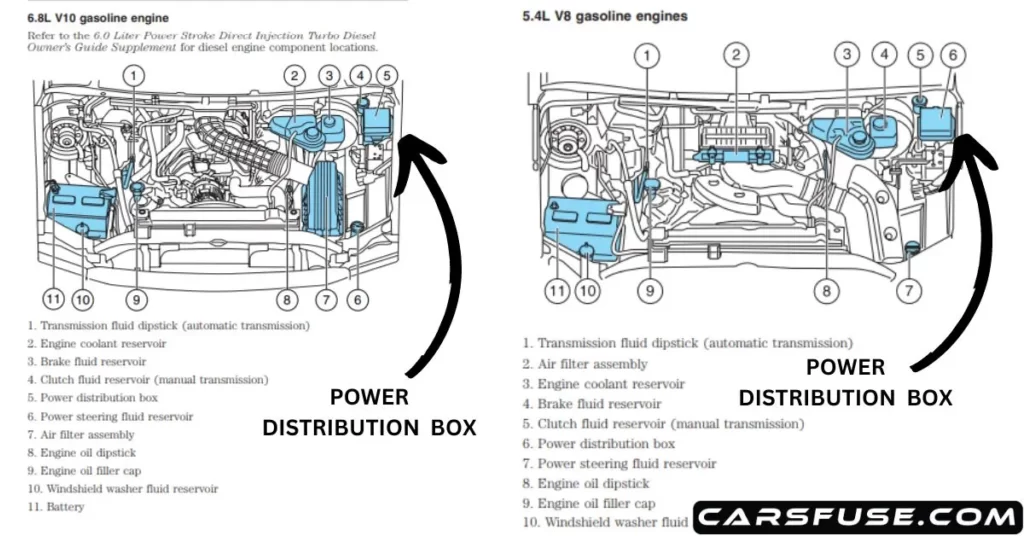
2007 Ford F450 Fuse Box Diagram (Power Distribution Box)
The engine compartment of the 2007 Ford F450 contains an essential component called the power distribution box. This box plays a vital role in protecting the main electrical systems of the vehicle. It is specifically designed to house high-current fuses that act as safeguards against potential overloads that could damage the vehicle’s electrical components.
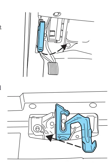
You need to open the hood to access the Power Distribution Box. Follow these steps:
- From within the vehicle, locate and pull the hood release handle situated beneath the lower left corner of the instrument panel.
- Proceed to the front of the vehicle and release the auxiliary latch positioned underneath the center-right area of the hood. Slide the handle to unlock the auxiliary latch.
- Gently raise the hood until the lift cylinders engage and securely hold it in the open position.
In situations where the vehicle’s battery has been disconnected and needs to be reconnected, it is highly recommended to consult the owner’s manual for detailed instructions.
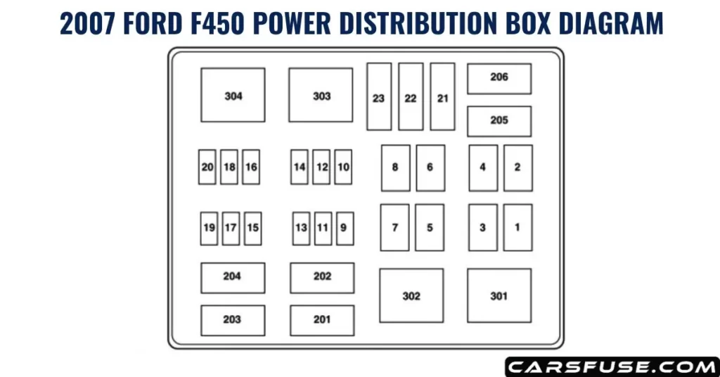
| Fuse/Relay Location | Fuse Amp Rating | Power Distribution Box Description |
| 1 | 30A* | Wipers |
| 2 | 40A* | Blower |
| 3 | 30A* | Electronic Shift on the Fly(ESOF) |
| 4 | — | Not used |
| 5 | 50A* | Injector Driver Module (IDM)(Diesel engine only) |
| 6 | — | Not used |
| 7 | — | Not used |
| 8 | — | Shunt |
| 9 | 20A** | Trailer tow turn signals |
| 10 | 10A** | Powertrain Control Module (PCM) keep alive power, Canister vent solenoid (gasoline engine only) |
| 11 | 10A** | Anti-lock Brake System (ABS) |
| 12 | 2A** | Brake pressure switch |
| 13 | 15A** | Daytime Running Lamps (DRL) |
| 14 | — | Not used |
| 15 | 15A** | IDM logic (Diesel engine only) |
| 16 | — | Not used |
| 17 | 10A** | A/C clutch |
| 18 | 10A** | IDM relay (Diesel engine only) |
| 19 | — | Not used |
| 20 | 10A** | Trailer tow back-up lamps |
| 21 | — | Not used |
| 22 | 60A*** | ABS (Coils) |
| 23 | 60A*** | ABS (Pump) |
| 201 | 1⁄2 ISO relay | Trailer tow right turn signal/stop lamp |
| 202 | 1⁄2 ISO relay | Trailer tow left turn signal/stop lamp |
| 203 | 1⁄2 ISO relay | A/C clutch |
| 204 | — | Not used |
| 205 | 1⁄2 ISO relay | DRL #1 |
| 206 | 1⁄2 ISO relay | DRL #2 |
| 301 | Full ISO relay | DRL #3 |
| 302 | — | Not used |
| 303 | Full ISO relay | Blower |
| 304 | High-current relay | IDM (Diesel engine only) |
| * Cartridge Fuse ** Mini Fuses *** Maxi fuse | ||
2007 Ford F450 Passenger Compartment Fuse Panel Diagram
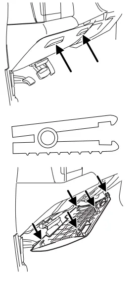
The passenger compartment Fuse Panel is located below and to the left of the steering wheel by the brake pedal. Remove the panel cover to access the fuses.
- Locate the fuse panel below and to the left of the steering wheel, near the brake pedal.
- Remove the panel cover by pulling it downward using the finger slots on top of the panel.
- Once the top clips disengage, let the panel fall gently.
- To remove a fuse, use the fuse puller tool provided on the fuse panel cover.
- Reinstall the cover by aligning and engaging the two hooked clips at the bottom onto the instrument panel.
- Lift the panel and firmly press the top clips into place to secure the cover.
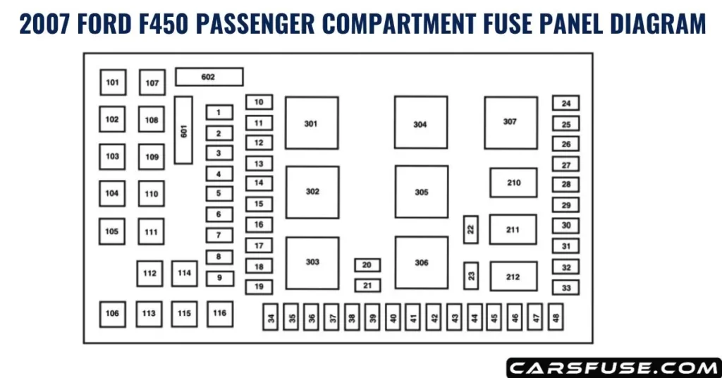
| Fuse/RelayLocation | Fuse AmpRating | Passenger Compartment FusePanel Description |
| 1 | 15A* | Adjustable pedals |
| 2 | 10A* | Cluster |
| 3 | 10A* | Upfitter #3 |
| 4 | 20A* | Power point (Instrument panel) |
| 5 | 10A* | Upfitter #4 |
| 6 | — | Not used |
| 7 | 30A* | High beam headlamps,Flash-to-pass |
| 8 | 20A* | Back-up lamps |
| 9 | — | Not used |
| 10 | — | Not used |
| 11 | 20A* | Radio (Main) |
| 12 | 20A* | Cigar lighter, OBD II |
| 13 | 5A* | Power mirrors |
| 14 | — | Not used |
| 15 | — | Not used |
| 16 | — | Not used |
| 17 | 15A* | Exterior lamps |
| 18 | 20A* | Flasher, Brake On-Off (BOO) lamps |
| 19 | 10A* | Body Security Module (BSM)(Security) |
| 20 | 15A* | Trailer tow Electric BrakeController (EBC) |
| 21 | 20A* | Heated seats |
| 22 | 20A* | Engine control |
| 23 | 20A* | Engine control (gasoline engine only)/Climate control (Diesel engine only) |
| 24 | 15A* | Tow haul, Blower relay, ElectronicAutomatic Temperature Control(EATC) |
| 25 | — | Not used |
| 26 | 10A* | Airbags |
| 27 | 15A* | Ignition switch RUN feed |
| 28 | 10A* | Trailer tow EBC logic |
| 29 | 10A* | Customer access |
| 30 | 15A* | High beam headlamps |
| 31 | 15A* | Starter relay |
| 32 | 5A* | Radio (start) |
| 33 | 15A* | Cluster, 4×4, Wipers |
| 34 | 10A* | BOO switch (Low current) |
| 35 | 10A* | Instrument cluster |
| 36 | — | Not used |
| 37 | 15A* | Horn |
| 38 | 20A* | Trailer tow park lamps |
| 39 | 15A* | Heated mirrors |
| 40 | 20A* | Fuel pump |
| 41 | 10A* | Instrument cluster |
| 42 | 15A* | Delayed accessory |
| 43 | 10A* | Fog lamps |
| 44 | — | Not used |
| 45 | 10A* | Ignition switch RUN/START feed |
| 46 | 10A* | Left-hand low beam headlamp |
| 47 | 10A* | Right-hand low beam headlamp |
| 48 | — | Not used |
| 101 | 30A** | Trailer tow EBC |
| 102 | 30A** | BSM (Door locks) |
| 103 | 30A** | Ignition switch |
| 104 | — | Not used |
| 105 | — | Not used |
| 106 | — | Not used |
| 107 | 20A** | Trailer tow battery charge |
| 108 | 30A** | Upfitter #1 |
| 109 | 30A** | Upfitter #2 |
| 110 | 30A** | Ignition switch |
| 111 | — | Not used |
| 112 | 30A** | Power seat (Driver) |
| 113 | 30A** | Starter |
| 114 | 30A** | Power seat (Passenger) |
| 115 | 20A** | Upfitter control |
| 116 | 30A** | Ignition switch |
| 210 | — | Not used |
| 211 | 1⁄2 ISO relay | Back-up lamps |
| 212 | — | Not used |
| 301 | Full ISO relay | Trailer tow battery charge |
| 302 | Full ISO relay | Powertrain Control Module (PCM) |
| 303 | — | Not used |
| 304 | — | Not used |
| 305 | Full ISO relay | Upfitter control |
| 306 | Full ISO relay | Delayed accessory |
| 307 | Full ISO relay | Starter |
| 601 | 30A circuit breaker | Delayed accessory, Power windows, Moonroof |
| 602 | — | Not used |
| * Mini fuse ** Cartridge fuse | ||
Tom Smith is a passionate car mechanic and automotive enthusiast, specializing in the intricate world of car fuse boxes. With years of hands-on experience under the hood, he has earned a reputation as a reliable expert in his field. As the founder and content creator of the popular blog website 'carsfuse.com,' Tom has dedicated himself to sharing his extensive knowledge of car fuse boxes and electrical systems with the world.