You drive one of the most reliable trucks ever: the 1997–2003 Ford F-150. It’s tough, but even a dependable truck can have small electrical issues—like a dead radio, a silent horn, or flickering lights—all caused by a tiny blown fuse.
Instead of guessing, wasting time, or going to a mechanic, you need a clear guide.
This guide gives you a simple, complete look at the 1997-2003 Ford F-150 fuse box diagram. You’ll see where the power goes and what each fuse controls, so you can quickly find the problem, replace the blown fuse, and get your F-150 running like new.
Note: In the event that you need to disconnect and reconnect the battery, it's important to note that certain features may require resetting. This step is necessary to restore their functionality.
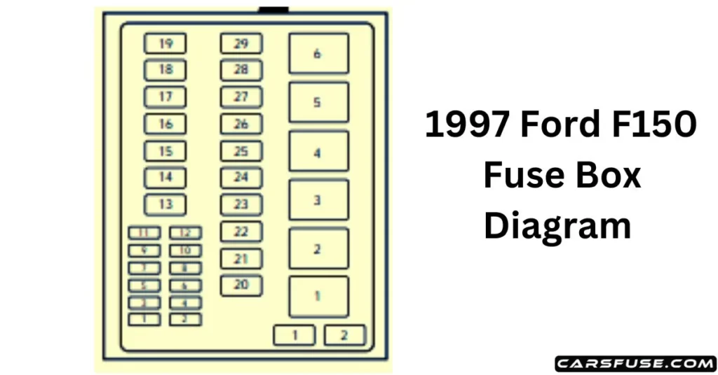
1997 FORD F150 FUSE BOX DIAGRAM
Position
Amps
Description
1
20
Trailer tow backup and tail lamps
2
10
Airbag diagnostic monitor
3
15
Power locks
4
15
Air suspension
5
20
Horn
6
15
Audio system
12
–
Not used
13
–
Not used
14
60/20
4WABS/rear anti-lock brake
15
50
Air suspension compressor
16
40
Trailer tow battery charge and stop/turn lamps
17
30
4WD transfer case, shift motor, and clutch
18
30
Driver power seat
19
20
Fuel pump
20
50
Instrument panel fuse panel ignition switch feed
21
50
Instrument panel fuse panel ignition switch feed
22
50
I/P fuse panel battery feed
23
40
I/P blower
24
30
PCM power
25
30
Power windows
26
–
Not used
27
–
Not used
28
30
Trailer tow electronic brake
29
–
Not used
Diodes
Position
Description
1
Rear ABS diode
2
PCM diode
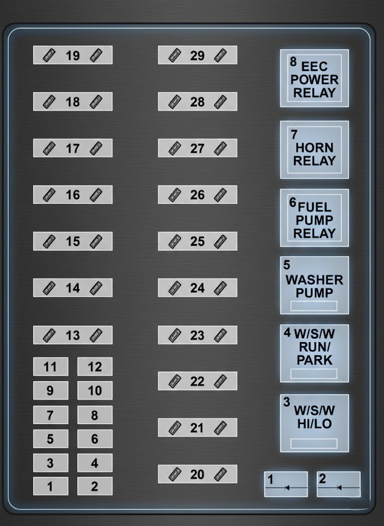
Relays
Position
Description
1
Windshield wipers HI/LO speed
2
Windshield wipers run/park relay
3
Washer pump relay
4
Fuel pump relay
5
Horn relay
6
PCM power relay
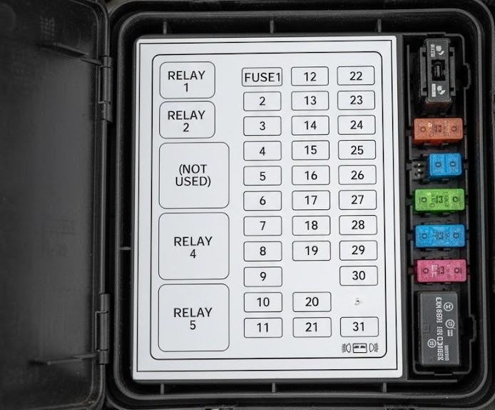
Instrument Fuse Panel
Position
Amps
Description
1
15
Stop/turn lamps and turn indicators
2
5
Instrument cluster
3
25
Cigarette lighter
4
5
Power mirrors, auto lamp, remote anti-theft/keyless entry, headlamp relay, and parking lamp relay
Digital Transmission Range (DTR) Sensor(A/T), Backup Lamp Switch (M/T), Daytime Running Lights (DRL)Module, Speed Control Servo/Amplifier Assembly, Heater-A/C Control Assembly, Blend Door Actuator
Park Lamp Relay, Trailer Electronic Brake Controller, Main Light Switch, Trailer Tow Run Relay, Front Park/Turn Lamps, License Lamps, Stop/Park/Turn Lamps, Tail/Side Marker Lamps (Power supplied through Main Light Switch)
19
10A
Instrument Cluster, Air Bag Diagnostic Monitor
20
5A
Powertrain Control Module (PCM), Generic Electronic Module (GEM)/CentralTimer Module (CTM)
Autolamp Module, Transmission Overdrive Control Switch
30
30A
Passive AntiTheft Transceiver, Cluster, Ignition Coils, Powertrain Control Module Relay
31
—
Not Used
Relay 1
—
Interior Lamp Relay
Relay 2
—
Battery Saver Relay
Relay 3
—
Not Used
Relay 4
—
One Touch Down Window Relay
Relay 5
—
ACC Delay Relay
2001 Ford F-150 Fuse Box Diagram
This Ford F150 model contains two fuse box layouts: Power Distribution Fuse Box and Passenger Compartment Fuse Box.
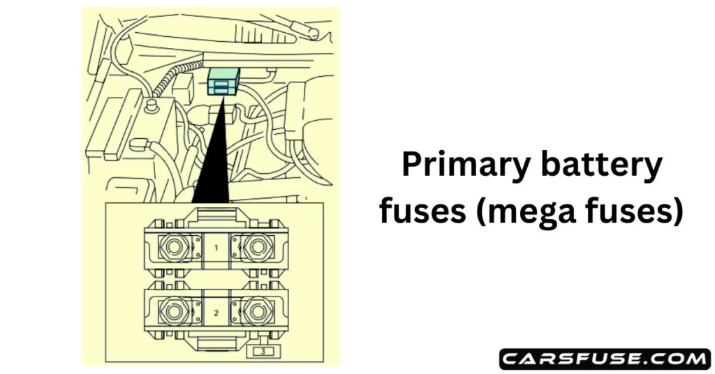
Power Distribution Fuse Box
Note: In the event that you need to disconnect and reconnect the battery, it's important to note that certain features may require resetting. This step is necessary to restore their functionality.

*Mini fuses/ **Maxi fuses
Spare fuse amperage may vary.
Fuse/Relay Location
Fuse AmpRating
Power Distribution Box Description
1
20A *
PowerPoint
2
30A*
Powertrain Control Module
3
30A*
Main Light Switch, Headlamp Relay, Multifunction Switch
4
—
Not Used
5
20A*
Trailer Tow Backup/Park Lamps
6
15A*
Main Light Switch, Park Lamp Relay
7
20A*
Horn
8
15A*
Power Door Locks, CSM, Lock Relays
9
15A*
Daytime Running Lamps (DRL), Fog Lamps
10
20A*
Fuel Pump
11
20A*
Alternator Field
12
20A*
Rear Auxiliary PowerPoint
13
15A*
A/C Clutch
14
—
Not Used
15
10A
Running Board Lamps (Supercrew only)
16
—
Not Used
17
—
Not Used
18
15A*
Powertrain Control Module, Fuel Injectors, Fuel Pump Relay, Mass Air Flow Sensor
19
10A*
Trailer/Camper Adapter (Right Stop and Right Turn Lamp)
20
10A*
Trailer/Camper Adapter (Left Stop and Left Turn Lamp)
Foglamp Relay and Foglamp Indicator, Main Light Switch (upstream)
28
10A
Left Side Low Beam Headlamp
29
5A
Autolamp Module, Transmission Overdrive Control Switch, Central Security Module, Belt Minder
30
30A
Passive Anti Theft Transceiver, Cluster, Ignition Coils, Powertrain Control Module Relay, Coil on Plugs, Radio Noise Capacitor, ECC Diode
31
—
Not Used
Relay 1
—
Interior Lamp Relay
Relay 2
—
Battery Saver Relay
Relay 3
—
Not Used
Relay 4
—
One Touch Down Window Relay
Relay 5
—
ACC Delay Relay
2002-2003 Ford F-150 Fuse Box Diagram
Ford F150 built in 2002 and 2003 features the same fuse box layout, and there are two boxes: Power Distribution Box and Passenger Compartment Fuse Panel.
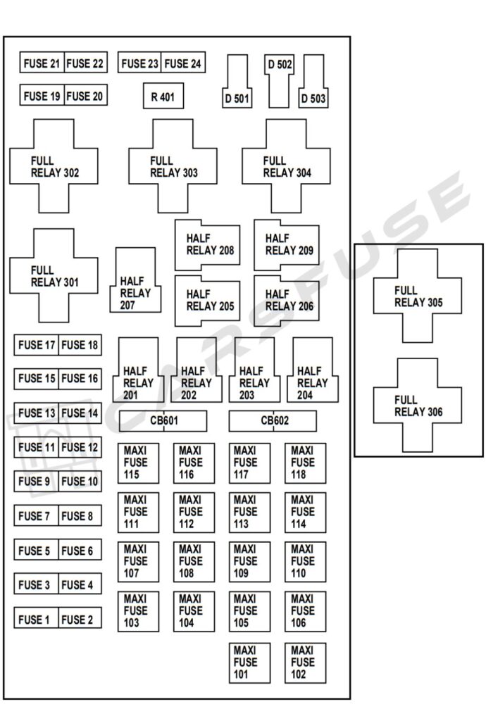
Power Distribution Fuse Box
Note: In the event that you need to disconnect and reconnect the battery, it's important to note that certain features may require resetting. This step is necessary to restore their functionality.

*Mini fuses /**Maxi fuses
Spare fuse amperage may vary.
Fuse/RelayLocation
Fuse AmpRating
Driver’s power seat, Adjustable pedal switch
1
20A *
Powerpoint
2
30A*
Powertrain Control Module (PCM)
3
30A*
Main light switch, Headlamp relay, Multifunction switch
4
—
Not used
5
20A*
Trailer tow backup/park lamps
6
15A*
Main light switch, Park lamp relay
7
20A*
Horn
8
15A*
Power door locks, Central Security Module (CSM), Lock relays (not used on SuperCrew)
9
15A*
Daytime Running Lamps (DRL), Fog lamps
10
20A*
Fuel pump
11
20A*
Alternator field
12
20A*
Rear auxiliary power point(SuperCrew only)
13
15A*
A/C clutch
14
—
Not used
15
10A
Running board lamps
16
—
Not used
17
—
Not used
18
15A*
PCM, Fuel injectors, Fuel pump relay, Mass airflow sensor
19
10A*
Trailer/Camper adapter (right stop/turn lamp)
20
10A*
Trailer/Camper adapter (left stop/turn lamp)
21
—
Not used
22
—
Not used
23
15A*
HEGO sensor, Automatic transmission
24
—
Not used
101
30A**
Trailer tow battery charge
102
50/20A**
Four-wheel Anti-lock Brake System (4WABS) module/Rear-wheel Anti-lock Brake System (RABS) module, Ignition switch
103
50A**
Central junction box
104
30A**
4×4 shift motor & clutch
105
40A**
Climate control front blower
106
20A**
Intercooler pump (supercharged engine only)
107
—
Not used
108
30A**
Trailer tow electric brake
109
—
Not used
110
30A**
Accessory delay relay (Not used on SuperCrew)
111
40A**
Ignition switch battery feed (start and run circuits)
112
30A**
Drivers power seat, Adjustable pedal switch
113
40A**
Ignition switch battery feed (run and accessory circuits)
114
—
Not used
115
20A**
Power door locks (SuperCrew only)
116
—
Not used
117
—
Not used
118
30A**
Heated seats
201
—
Trailer tow park lamp relay
202
—
Front wiper run/park relay
203
—
Trailer tow backup lamp relay
204
—
A/C clutch relay
205
—
Horn relay
206
—
Fog lamp relay
207
—
Front washer pump relay
208
—
Intercooler pump relay(supercharged engine only)
209
—
Front wiper HI/LO relay
301
—
Fuel pump relay
302
—
Trailer tow battery charge relay
303
—
Not used
304
—
PCM relay
305
—
Fuel pump HI/LO relay(supercharged engine only)
306
—
Inertia switch relay (supercharged engine only)
401
—
Not used
501
—
PCM diode
502
—
A/C compressor diode
503
—
Not used
601
CB
Power windows, Moonroof(SuperCrew only)
602
—
Not used
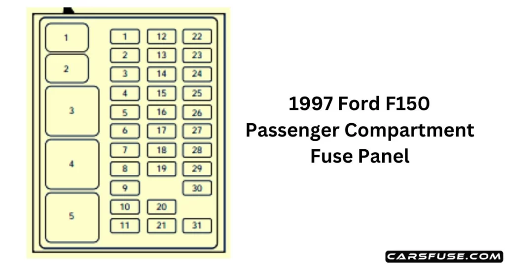
Passenger Compartment Fuse Panel
Fuse/RelayLocation
Fuse AmpRating
Passenger Compartment FusePanel Description
1
15A
Audio
2
5A
Powertrain Control Module(PCM), Cluster
3
20A
Cigar lighter, Data link connector
4
5A
Power mirror switch, Mirror turn signal relays
5
15A
Speed control module, Reverse lamp, Climate mode switch, Daytime Running Lamps (DRL) relay, Digital Transmission Range(DTR) sensor
6
5A
Cluster, Brake shift interlock solenoid, GEM
7
—
Not used
8
5A
Radio, Remote entry module, GEM, In-vehicle entertainment system (SuperCrew only)
9
—
Not used
10
—
Not used
11
30A
Front washer pump relay, Wiper run/park relay, Wiper HI/LO relay, Windshield wiper motor
Always disconnect the negative battery terminal before removing fuses.
Never replace a blown fuse with a higher amp rating — this can damage wiring or cause a fire.
Use a fuse puller or needle-nose pliers for safety.
Label replaced fuses for future reference.
Frequently Asked Questions (FAQs)
Why does the radio fuse blow in the F-150?
The radio fuse can blow due to: Short circuit: Damaged or frayed wires, or the radio itself, can cause excess current. Extra devices: Adding amplifiers or accessories on the same circuit can overload the fuse. Wrong fuse: Using a fuse with lower amperage than recommended. Radio defect: A faulty radio may draw too much power. Electrical issues: Problems like a bad alternator can cause voltage spikes that blow the fuse.
Why does the cigarette lighter (power socket) fuse blow in the F-150?
The fuse can blow due to: Overload: Devices that draw too much power (e.g., chargers, compressors, inverters). Short circuit: Damaged wires or contact with metal can cause excess current. Faulty adapters: Low-quality or defective adapters may overload the circuit. Wrong fuse: Using a fuse with lower amperage than recommended.
Why does the headlight fuse blow in the F-150?
The fuse can blow due to: Short circuit: Damaged or frayed wires touching metal. Defective bulb: A faulty or burned-out bulb can overload the fuse. Faulty switch: A bad headlight switch can cause current spikes. Extra components: Added lights or modifications can overload the circuit.