This article is here to help you understand the 1997 Ford F150 fuse box diagram. We’ll go through each fuse and explain what it does, making it easier for you to use your electrical system with confidence.
Table of Contents
Note: All information contained in this Quick Reference Guide was accurate at the time of duplication. For detailed operating and safety information, please consult your Owner’s Manual.
The power distribution box, which houses high-current fuses, is situated in the engine compartment of your vehicle. Lift the cover towards the left of the vehicle to access the power distribution box. These fuses play a crucial role in safeguarding the main electrical systems from overloads, ensuring their proper functioning. The high-current fuses within the power distribution box are coded using a specific system.
Note: In the event that you need to disconnect and reconnect the battery, it's important to note that certain features may require resetting. This step is necessary to restore their functionality.
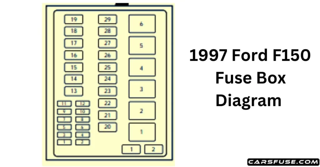
1997 FORD F150 FUSE BOX DIAGRAM
Position
Amps
Description
1
20
Trailer tow backup and tail lamps
2
10
Airbag diagnostic monitor
3
15
Power locks
4
15
Air suspension
5
20
Horn
6
15
Audio system
12
–
Not used
13
–
Not used
14
60/20
4WABS/rear anti-lock brake
15
50
Air suspension compressor
16
40
Trailer tow battery charge and stop/turn lamps
17
30
4WD transfer case shift motor and clutch
18
30
Driver power seat
19
20
Fuel pump
20
50
Instrument panel fuse panel ignition switch feed
21
50
Instrument panel fuse panel ignition switch feed
22
50
I/P fuse panel battery feed
23
40
I/P blower
24
30
PCM power
25
30
Power windows
26
–
Not used
27
–
Not used
28
30
Trailer tow electronic brake
29
–
Not used
Diodes
Position
Description
1
Rear ABS diode
2
PCM diode
Relays
Position
Description
1
Windshield wipers HI/LO speed
2
Windshield wipers run/park relay
3
Washer pump relay
4
Fuel pump relay
5
Horn relay
6
PCM power relay
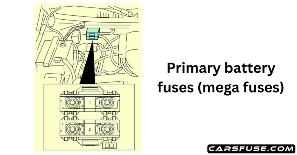
1997 Ford F150 Primary battery fuses (mega fuses)
To access the primary battery fuses, you can locate them beneath the cover labeled “PRIMARY BATTERY FUSE,” positioned adjacent to the starter relay.
Note: For optimal maintenance and safety, it is strongly advised to entrust the servicing of Mega fuses exclusively to a skilled and certified service technician.
1997 FORD F150 FUSE BOX DIAGRAM
Location
Amperage
Description
1
175
Power network box mega fuse
2
175
Alternator mega fuse
3
20
Alternator field mini fuse
1997 Ford F150Engine mini fuse panel
To find the mini fuse panel, you will need to locate the power distribution box. The mini fuse panel is positioned behind the power distribution box. It is crucial to emphasize that any maintenance or inspection of the mini fuse panel should only be carried out by qualified individuals.
1997 FORD F150 FUSE BOX DIAGRAM
Location
Amperage
Description
1
5
Powertrain control module (PCM)
2
20
Trailer tow stop/turn lamps
3
–
Not used
4
–
Not used
5
–
Not used
6
–
Not used
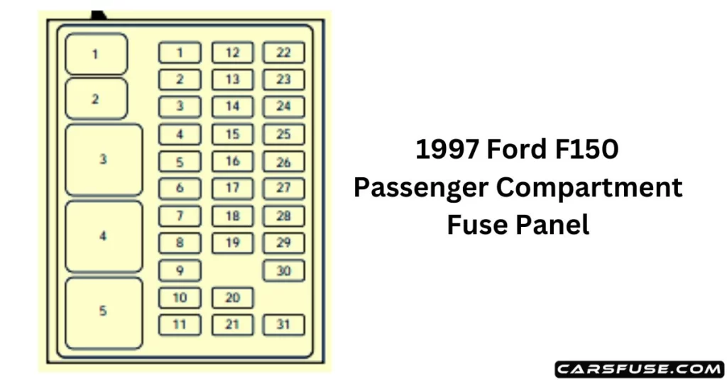
1997 Ford F150 Instrument Fuse PanelDiagram
Situated conveniently beneath and to the left of the steering wheel, in close proximity to the brake pedal, lies the fuse panel, which acts as the central hub for all the fuses in your vehicle. Once you remove the panel cover, you can effortlessly reach this essential component. To facilitate a seamless process of replacing fuses, providing you with greater ease in upkeeping and diagnosing your electrical system.
1997 FORD F150 FUSE BOX DIAGRAM
Position
Amps
Description
1
15
Stop/turn lamps and turn indicators
2
5
Instrument cluster
3
25
Cigarette lighter
4
5
Power mirrors, auto lamp, remote anti-theft/keyless entry, headlamp relay, and parking lamp relay
Tom Smith is a passionate car mechanic and automotive enthusiast, specializing in the intricate world of car fuse boxes. With years of hands-on experience under the hood, he has earned a reputation as a reliable expert in his field. As the founder and content creator of the popular blog website 'carsfuse.com,' Tom has dedicated himself to sharing his extensive knowledge of car fuse boxes and electrical systems with the world.