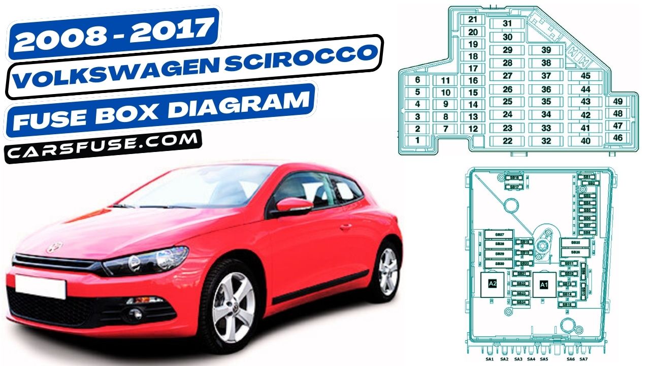
The Volkswagen Scirocco is a sporty two-door coupe that was produced from 2008 to 2017. It is powered by a variety of engines, including gasoline and diesel. The Scirocco has two fuse boxes, one located in the engine bay and one located in the passenger compartment.
If a fuse blows in the Scirocco, it will need to be replaced. To replace a fuse, first, locate the fuse box that is affected. Then, locate the blown fuse. The blown fuse will be blackened or melted. Carefully remove the blown fuse and replace it with a new fuse of the same amperage.
In this blog, we will explore the Volkswagen Scirocco Fuse Box Diagram that is beneficial for you to find, and replace blown fuses, or troubleshoot fuse-related issues.
Table of Contents
Instrument panel
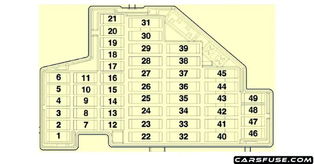
| Fuse Number | Fuse Amp. Rating | Function/component |
|---|---|---|
| 1 | 10A | Tyre Pressure Monitoring System button TCS and ESP button Start/Stop operation switch Reversing light switch High-pressure sender Air quality sensor Oil level and oil temperature sender Climatronic control unit Air conditioning system control unit Driver-side easy entry control unit Seat occupied recognition control unit Automatic anti-dazzle interior mirror Left washer jet heater element (2008-2013) Right washer jet heater element (2008-2013) |
| 2 | 10A | Light switch ABS control unit Brake light switch Electronically controlled damping control unit The control unit in the dash panel insert Power steering control unit Voltage stabiliser Data bus diagnostic interface Fuel pump control unit Selector lever sensors control unit Engine control unit Mechatronic unit for a dual-clutch gearbox |
| 3 | 5A | Airbag control unit Front passenger airbag deactivated warning lamp |
| 4 | 5A | 2008: Onboard supply control unit Terminal 30 voltage supply relay 2009-2013: Dual-tone horn relay 2014-2017: Additional instruments (without start/stop) |
| 5 | 10A | 2014-2017: Output module for left headlight Left headlight range control motor Left dipped beam screen |
| 6 | 10A | 2014-2017: Output module for the right headlight Right headlight range control motor Right-dipped beam screen |
| 7 | – | – |
| 8 | – | – |
| 9 | – | – |
| 10 | – | – |
| 11 | – | – |
| 12 | 10A | Driver door control unit Front passenger door control unit (2008-2013) |
| 13 | 5A/10A | Light switch Rain and light sensor Reversing camera 16-pin connector, self-diagnosis connection Heated rear window relay Dual tone horn relay (2010-2017) |
| 14 | 5A/10A | 2009-2017: Entry and start authorization control unit |
| 15 | 5A/7.5A | Heater control unit Headlight washer system relay Climatronic control unit Air conditioning system control unit Selector lever sensors control unit Parking aid control unit (2008) ABS control unit (2008) |
| 16 | 10A | 2014-2017: Front passenger door control unit |
| 17 | 5A | 2009-2014: Control unit with display for radio and navigation Radio 2015-2017: A display unit for front information display and operating unit control unit with control unit 1 for information electronics (with start/stop) |
| 18 | – | – |
| 19 | – | – |
| 20 | 10A | 2009-2017: A control unit for electronic steering column lock |
| 21 | 10A | 2009-2017: Control unit for electronic steering column lock |
| 22 | 40A | Fresh air blower control unit |
| 23 | 30A | Driver door control unit (LHD) Front passenger door control unit (RHD) |
| 24 | 30A | 2009-2017: Onboard supply control unit |
| 25 | 25A/30A | Heated rear window relay Onboard supply control unit (2008) |
| 26 | – | – |
| 27 | 15A/20A | Fuel pump relay Fuel pump control unit Relay for supplementary fuel pump |
| 28 | 15A | 2009-2014: Control unit with display for radio and navigation Radio 2015-2017: Display unit for front information display and operating unit control unit with control unit 1 for information electronics (with start/stop) |
| 29 | – | – |
| 30 | – | – |
| 31 | 20A | 2010-2014: Vacuum pump for brakes |
| 32 | 30A | 2010-2017: Driver door control unit (RHD) Front passenger door control unit (LHD) |
| 33 | 30A | Control unit for tilting sunroof |
| 34 | 15A | Driver seat lumbar support adjustment switch Front passenger seat lumbar support adjustment switch |
| 35 | 10A/15A | Electronically controlled damping control unit |
| 36 | 20A | Headlight washer system pump |
| 37 | 30A | Heated front seats control unit |
| 38 | 20A | 2008: Convenience system central control unit 2009-2017: Onboard supply control unit |
| 39 | – | – |
| 40 | 40A | Heater/heat output switch Air conditioning system control unit Blower relay |
| 41 | 15A | Rear window wiper motor |
| 42 | 20A | Blocking diode 2 Cigarette lighter 12V socket |
| 43 | – | – |
| 44 | – | – |
| 45 | – | – |
| 46 | – | – |
| 47 | 10A | Heated front seat control unit |
| 48 | 5A | 2009-2017: Control unit in dash panel insert (with start/stop) |
| 49 | 5A | 2014-2017: Additional instruments (with start/stop) |
Fuses under the dash panel (driver’s side)
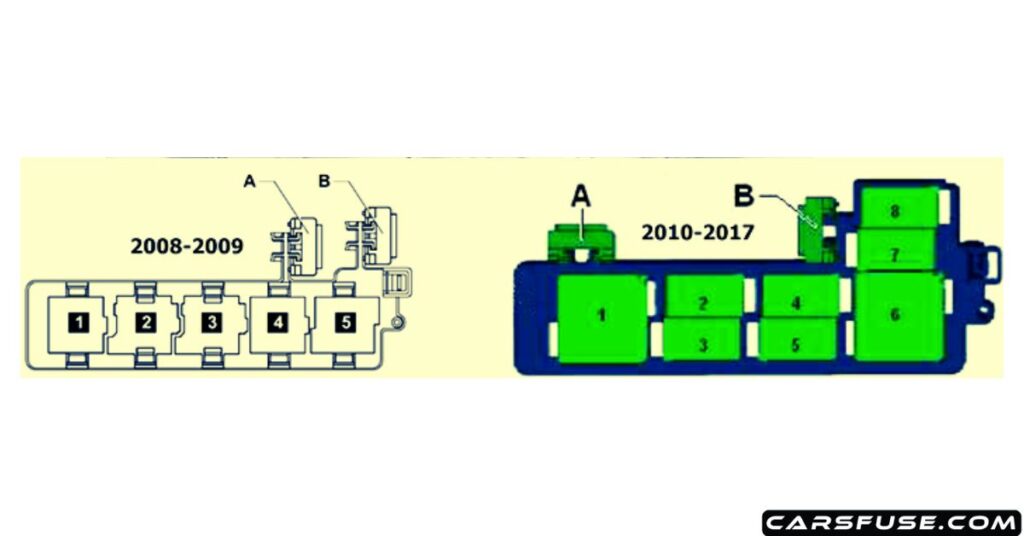
| Relay Number | Fuse Amp. Rating | Function/component |
|---|---|---|
| 1 | 2010-2017: Relay carrier on top of onboard supply control unit | |
| A | 20A | 2008-2009: Driver seat adjustment thermal fuse 1 |
| B | 20A | 2010-2017: Driver seat adjustment thermal fuse 1 |
Engine Compartment Fuse Box
Version 1 (Low)
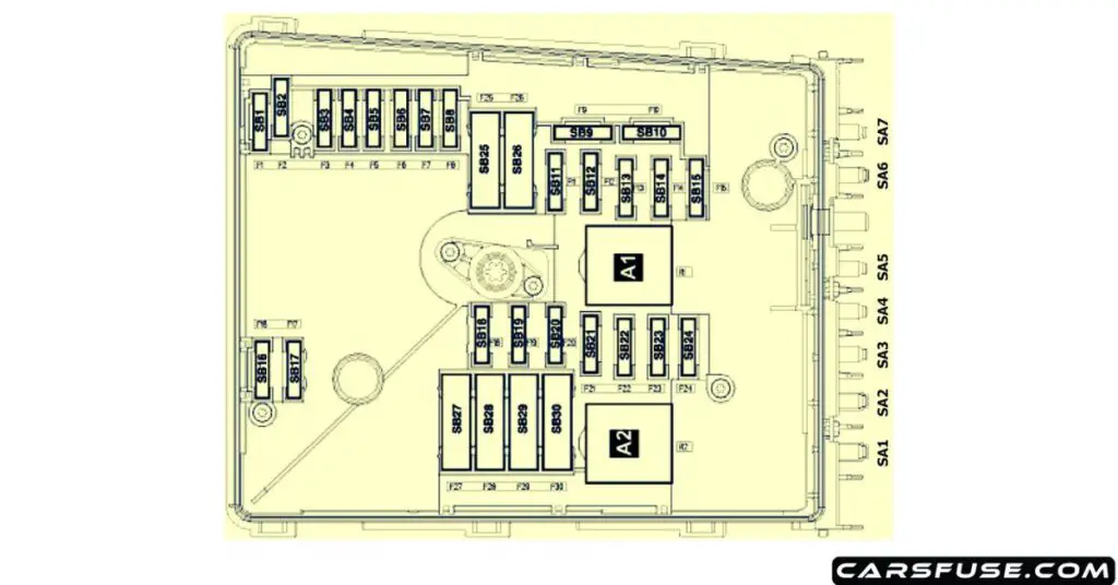
| Fuse Number | Fuse Amp. Rating | Function/component |
|---|---|---|
| F1 | – | – |
| F2 | 30A | Mechatronic unit for dual clutch gearbox |
| F3 | 5A | Battery monitor control unit (with start/stop) Onboard supply control unit |
| F4 | 20A/30A | ABS control unit |
| F5 | 15A | 2008: Mechatronic unit for a dual-clutch gearbox 2009-2017: Terminal 15 voltage supply relay 2 |
| F6 | 5A | Voltage stabilizer (with start/stop) Display unit for front information display and operating unit control unit with control unit 1 for information electronics (without start/stop) Radio (2008-2014) |
| F7 | 40A | The control unit in the dash panel insert (without start/stop) Steering column electronics control unit |
| F8 | 15A/25A | Mechatronic unit for a dual-clutch gearbox |
| F9 | 5A | Emergency call module control unit and communication unit (without start/stop) |
| F10 | 10A/5A | Engine control unit Main relay |
| F11 | – | – |
| F12 | 5A | Data bus diagnostic interface |
| F13 | 15A/30A | Engine control unit |
| F14 | 15A/20A | Ignition coil 1~4 with the output stage Camshaft control valve 1 Fuel pressure regulating valve Fuel metering valve injector 2, cylinder 1~4 Exhaust cam actuator A for cylinders 1~4 Exhaust cam actuator B for cylinders 1~4 |
| F15 | 5A/10A/15A | Ignition coil 1~4 with the output stage Camshaft control valve 1 Fuel pressure regulating valve Fuel metering valve injector 2, cylinder 1~4 Exhaust cam actuator A for cylinders 1~4 Exhaust cam actuator B for cylinders 1~4 |
| F16 | 30A | 2008: ABS control unit 2009-2017: Onboard supply control unit |
| F17 | 15A | Lambda probe Lambda probe after the catalytic converter Low heat output relay High heat output relay Fuel pump relay Relay for supplementary fuel pump Automatic glow period control unit |
| F18 | 30A | Amplifier Digital sound package control unit |
| F19 | 30A | Wiper motor control unit Windscreen wiper motor |
| F20 | 10A/15A | Horn and dual tone horn Dual-tone horn relay |
| F21 | 10A/15A | Ignition coil 1~4 with the output stage Coolant circulation pump Continued coolant circulation pump Fuel metering valve |
| F22 | 5A | Clutch position sender (with start/stop) Brake light switch |
| F23 | 5A/10A/15A | Air mass meter (with start/stop) Sender 1 for secondary air pressure Continued coolant circulation relay Auxiliary engine coolant pump relay Charge pressure control solenoid valve Activated charcoal filter solenoid valve 1 Camshaft control valve 1 Exhaust camshaft control valve 1 Fuel metering valve Oil pressure control valve Coolant valve for cylinder head Coolant pump Circulation pump |
| F24 | 10A | Oil pressure switch for reduced oil pressure Oil level and oil temperature sender Radiator fan control unit Low heat output relay High heat output relay Engine component current supply relay Charge pressure control solenoid valve Activated charcoal filter solenoid valve 1 Camshaft control valve 1 Turbocharger air recirculation valve Intake manifold flap valve Oil pressure control valve Piston cooling jet control valve Radiator fan Radiator fan 2 Charge air cooling pump Auxiliary pump for heating |
| F25 | 40A | ABS control unit ABS hydraulic pump Onboard supply control unit (2008) |
| F26 | 30A | Onboard supply control unit |
| F27 | 50A | Automatic glow period control unit |
| F28 | 30A | 2008: Terminal 15 voltage supply relay 2 |
| F29 | 50A | Fuses on fuse holder C (instrument panel): #32, 33, 34, 35, 36, 37 Driver seat adjustment thermal fuse 1 |
| F30 | 40/50A | X-contact relief relay Fuse 40 on fuse holder C (instrument panel): #40, 41, 42 |
| SA1 | 150A/200A | Alternator |
| SA2 | 80A | Power steering control unit Electromechanical power steering motor |
| SA3 | 50A | Radiator fan control unit Radiator fan Radiator fan 2 |
| SA4 | 80A | 2008: Auxiliary air heater control unit (CBDB) Low heat output relay 2009-2017: High heat output relay |
| SA5 | 80A | Terminal 30 connection, fuse holder C |
| SA6 | 40A | 2008: High heat output relay (CBDB) 2009-2017: Low heat output relay |
| SA7 | – | – |
Version 2 (High)
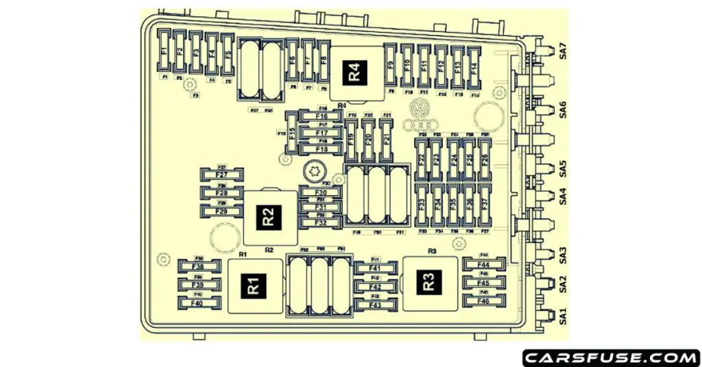
| Fuse Number | Fuse Amp. Rating | Function/component |
|---|---|---|
| F1 | 30A/40A | Onboard supply control unit |
| F2 | 20A | ABS control unit |
| F3 | – | – |
| F4 | 5A | Battery monitor control unit (with start/stop) Onboard supply control unit |
| F5 | 15A | Horn and dual-tone horn Dual-tone horn relay |
| F6 | – | not assigned |
| F7 | 15A | Fuel pressure regulating valve |
| F8 | – | not assigned |
| F9 | 10A | Charge pressure control solenoid valve Activated charcoal filter solenoid valve 1 Turbocharger air recirculation valve |
| F10 | 10A | 2009-2013: Air mass meter |
| F11 | 10A | Lambda probe heater |
| F12 | 10A | Horn and dual tone horn Dual-tone horn relay |
| F13 | 15A | Lambda probe 1 heater after the catalytic converter Lambda probe 2 heaters after the catalytic converter |
| F14 | – | – |
| F15 | 10A | Coolant circulation pump Continued coolant circulation pump |
| F16 | – | – |
| F17 | 5A | Voltage stabilizer (with start/stop) Display unit for front information display and operating unit control unit with control unit 1 for information electronics (without start/stop) Radio (2009-2014) |
| F18 | 30A | Amplifier |
| F19 | 15A/25A | Mechatronic unit for dual-clutch gearbox |
| F20 | 5A | Telephone control unit (2009-2014) Emergency call module control unit and communication unit (without start/stop) (2014-2017) |
| F21 | – | – |
| F22 | – | – |
| F23 | 10A | Engine control unit Main relay |
| F24 | 5A | Data bus diagnostic interface |
| F25 | – | – |
| F26 | – | – |
| F27 | 5A | Exhaust flap 1 valve |
| F28 | 15A | Engine control unit |
| F29 | 5A | Auxiliary engine coolant pump relay |
| F30 | – | – |
| F31 | 30A | Wiper motor control unit Windscreen wiper motor |
| F32 | – | – |
| F33 | – | – |
| F34 | – | – |
| F35 | – | – |
| F36 | – | – |
| F37 | – | – |
| F38 | 10A | Oil pressure switch for reduced oil pressure Oil level and oil temperature sender – Radiator fan control unit Low heat output relay High heat output relay Engine component current supply relay Charge pressure control solenoid valve Activated charcoal filter solenoid valve 1 Camshaft control valve 1 Turbocharger air recirculation valve Intake manifold flap valve Oil pressure control valve Piston cooling jet control valve Radiator fan Radiator fan 2 Charge air cooling pump Auxiliary pump for heating |
| F39 | 5A | Clutch position sender (with start/stop) Brake light switch |
| F40 | 20A | The control unit in dash panel insert (without start/stop) Steering column electronics control unit |
| F41 | – | – |
| F42 | 5A | Engine component current supply relay |
| F43 | – | – |
| F44 | – | – |
| F45 | – | – |
| F46 | – | – |
| F47 | 30A | Onboard supply control unit |
| F48 | 30A/40A | ABS control unit |
| F49 | 40A | Terminal 15 voltage supply relay 2 |
| F50 | – | – |
| F51 | – | – |
| F52 | 40A/50A | 2009-2013: X-contact relief relay 2014-2017: X-contact relief relay Fuses on fuse holder C (instrument panel): ~40, 41, 42 |
| F53 | 50A | 2009-2013: Fuse #32 on fuse holder C (instrument panel) 2014-2017: Fuses on fuse holder C (instrument panel): #32, 33, 34, 35, 36, 37 Driver seat adjustment thermal fuse 1 |
| F54 | – | – |
| SA1 | 150A/200A | Alternator |
| SA2 | 80A | Power steering control unit Electromechanical power steering motor |
| SA3 | 50A | Radiator fan control unit Radiator fan |
| SA4 | – | – |
| SA5 | 80A | Terminal 30 connection, fuse holder C |
| SA6 | – | – |
| SA7 | – | – |
Next Post: 2016-2020 Volkswagen Touran Fuse Box Diagram
Tom Smith is a passionate car mechanic and automotive enthusiast, specializing in the intricate world of car fuse boxes. With years of hands-on experience under the hood, he has earned a reputation as a reliable expert in his field. As the founder and content creator of the popular blog website 'carsfuse.com,' Tom has dedicated himself to sharing his extensive knowledge of car fuse boxes and electrical systems with the world.

