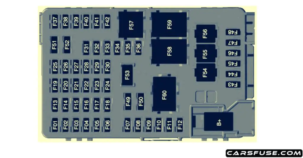
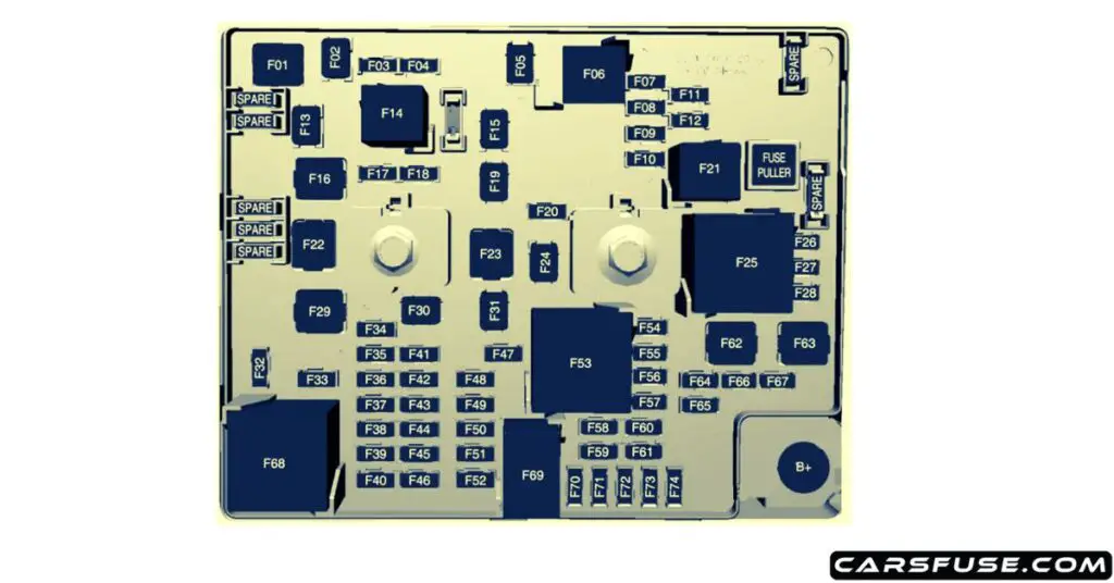
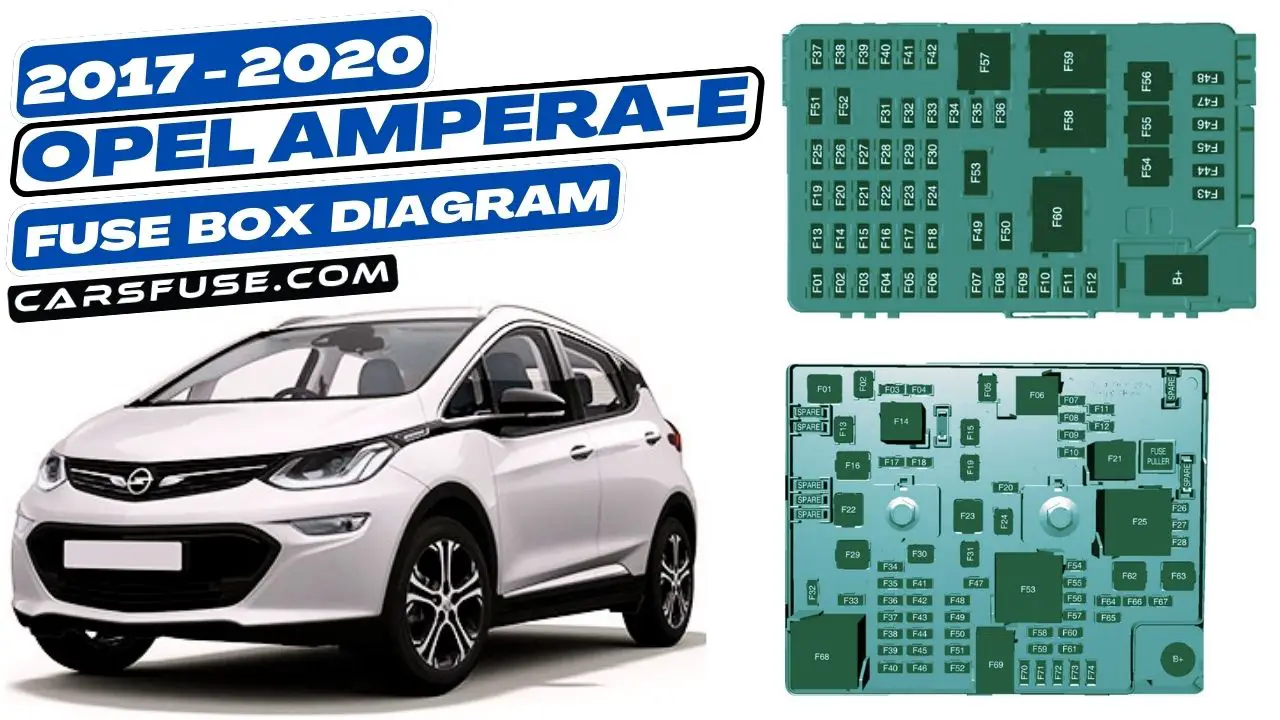
The Opel Ampera-e is an electric car that was produced from 2017 to 2020. It has two fuse boxes, one located in the passenger compartment and one located in the engine compartment. This blog post will provide diagrams of both fuse boxes, as well as a description of each fuse and relay.
Table of Contents
Instrument Panel
The passenger compartment fuse box is located under the dashboard on the driver’s side. To access it, you need to remove the protective cover. The fuse box contains 28 fuses, which are labeled with their respective amperage ratings and functions.

| Fuse Number | Protected Components |
|---|---|
| 1 | Video processing module |
| 2 | Indicator light solar sensor |
| 3 | Side blind zone alert |
| 4 | Passive entry, passive start |
| 5 | Central gateway module |
| 6 | Body control module 4 |
| 7 | Body control module 3 |
| 8 | Body control module 2 |
| 9 | Body control module 1 |
| 10 | Trailer interface module 1 |
| 11 | Amplifier |
| 12 | Body control module 8 |
| 13 | Data link connector 1 |
| 14 | Automatic parking assist |
| 15 | 2016-2017: Data link connector 2 |
| 16 | Single power inverter module 1 |
| 17 | Body control module 6 |
| 18 | Body control module 5 |
| 19 | – |
| 20 | – |
| 21 | – |
| 22 | – |
| 23 | USB |
| 24 | Wireless charging module |
| 25 | Reflected LED alert display |
| 26 | Heated steering wheel |
| 27 | – |
| 28 | Instrument cluster 2 |
| 29 | Trailer interface module 2 |
| 30 | Headlight levelling device |
| 31 | OnStar |
| 32 | – |
| 33 | Heating, ventilation, and air conditioning module |
| 34 | – |
| 35 | Instrument panel cluster 1 |
| 36 | Regen on demand / Radio |
| 37 | – |
| 38 | – |
| 39 | – |
| 40 | – |
| 41 | – |
| 42 | – |
| 43 | Body control module 7 |
| 44 | Sensing and diagnostic module |
| 45 | Front camera module |
| 46 | Vehicle integration control module |
| 47 | Single power inverter module 2 |
| 48 | Electric steering column lock |
| 49 | Auxiliary jack |
| 50 | Steering wheel controls |
| 51 | Steering wheel controls backlighting |
| 52 | Smartphone remote function module |
| 53 | Auxiliary power outlet |
| 54 | – |
| 55 | Logistic |
| 56 | – |
| 57 | – |
| 58 | Logistics relay |
| 59 | – |
| 60 | Accessory/Retained accessory power relay |
Engine Compartment
The engine compartment fuse box is located on the left side of the engine compartment. To access it, you need to remove the protective cover. The fuse box contains 10 fuses, which are also labeled with their respective amperage ratings and functions.

| Fuse Number | Protected Components |
|---|---|
| 1 | – |
| 2 | Power window rear |
| 3 | – |
| 4 | Rechargeable energy storage system 1 |
| 5 | – |
| 6 | – |
| 7 | Left high-beam headlight |
| 8 | Right high-beam headlight |
| 9 | Left low-beam headlight |
| 10 | Right low-beam headlight |
| 11 | Horn |
| 12 | – |
| 13 | Front wiper motor driver |
| 14 | Tailgate |
| 15 | Front wiper motor co-driver |
| 16 | Electronic brake control module supply electronics |
| 17 | Rear wiper |
| 18 | Tailgate |
| 19 | Seat module front |
| 20 | Washer |
| 21 | 2016-2017: HID light |
| 22 | Linear power module |
| 23 | Electronic brake control module supply motor |
| 24 | Seat module rear |
| 25 | Powertrain |
| 26 | Transmission range control module |
| 27 | Aero shutter |
| 28 | Auxiliary oil pump |
| 29 | E-booster motor source |
| 30 | Front power windows |
| 31 | In-panel bussed electrical centre |
| 32 | Rear window defogger |
| 33 | Heated exterior rear view mirror |
| 34 | Pedestrian friendly alert function |
| 35 | – |
| 36 | – |
| 37 | Current sensor |
| 38 | Rain sensor |
| 39 | – |
| 40 | E-booster (ECU) |
| 41 | Power line communication module |
| 42 | Automatic occupant sensing |
| 43 | Window switch |
| 44 | Rechargeable energy storage system |
| 45 | Vehicle integration control module |
| 46 | Integrated chassis control module |
| 47 | Headlight levelling device |
| 48 | Integrated chassis control module |
| 49 | Interior rear view mirror |
| 50 | – |
| 51 | E-booster |
| 52 | Rear camera |
| 53 | Run/Crank |
| 54 | A/C control module |
| 55 | Rechargeable energy storage system pump |
| 56 | – |
| 57 | Power electronics coolant pump |
| 58 | Engine control module |
| 59 | Electric steering column lock |
| 60 | HVAC electric heater |
| 61 | On-board charging module |
| 62 | Transmission range control module 1 |
| 63 | Electric cooling fan |
| 64 | Engine control module |
| 65 | Auxiliary heater pump |
| 66 | Powertrain relay |
| 67 | Drive unit controller |
| 68 | Rear window defogger |
| 69 | Second run/Crank relay |
| 70 | A/C control module |
| 71 | – |
| 72 | Transmission range control module |
| 73 | Single power inverter module |
| 74 | – |
Conclusion
This blog post has provided diagrams and descriptions of the fuse boxes in the Opel Ampera-e. By understanding the location and function of each fuse and relay, you can troubleshoot electrical problems in your car more easily.
Here are some additional tips for troubleshooting electrical problems in your Opel Ampera-e:
- Check the fuse box diagrams to see if a fuse has blown.
- Check the relays to see if they are faulty.
- Test the wiring harnesses for damage.
- Inspect the connectors for corrosion or loose connections.
- If you are still unable to identify the problem, take your car to a qualified mechanic.
Next Post: 2011-2015 Skoda Citigo Fuse Box Diagram
Tom Smith is a passionate car mechanic and automotive enthusiast, specializing in the intricate world of car fuse boxes. With years of hands-on experience under the hood, he has earned a reputation as a reliable expert in his field. As the founder and content creator of the popular blog website 'carsfuse.com,' Tom has dedicated himself to sharing his extensive knowledge of car fuse boxes and electrical systems with the world.

