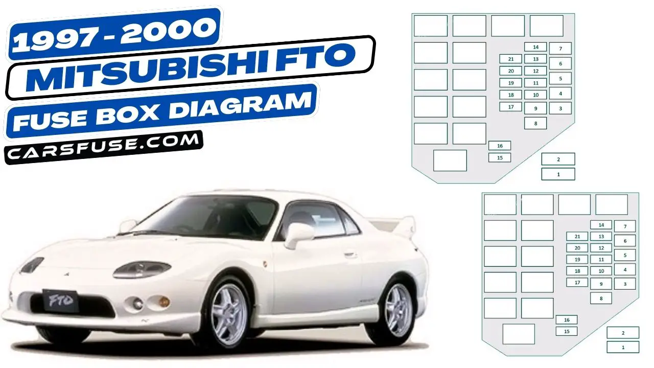
The Mitsubishi FTO is a sports car that was produced from 1994 to 2000. It was available with a variety of engines, including a 2.0-liter turbocharged four-cylinder engine. The FTO has many electrical components, and the fuse box is responsible for protecting these components from electrical overloads.
The fuse boxes in the Mitsubishi FTO are labeled with a diagram that shows the location of each fuse and its corresponding amperage rating. This diagram can be used to identify the fuse that needs to be replaced if an electrical component stops working.
Table of Contents
Fuse Box Location
There are two fuse boxes in the Mitsubishi FTO: one in the engine compartment and one in the passenger compartment. The engine compartment fuse box is located on the driver’s side, near the battery. The passenger compartment fuse box is located under the dashboard, on the driver’s side.
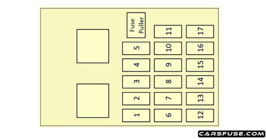
Passenger Compartment

| Fuse Number | Fuse Amp. Rating | Protected Components |
|---|---|---|
| 1 | 15A | Door lock-ECU |
| 2 | 10A | TCL-ECU |
| 3 | 10A | A/T-ECU, A/T indicator lamp, output/input shaft speed sensor, back-up lamp, buzzer-ECU |
| 4 | 10A | SRS-ECU, turn-signal and hazard flasher unit |
| 5 | – | – |
| 6 | 30A | Defogger |
| 7 | – | – |
| 8 | 10A | SRS-ECU, combination meter, sunroof-ECU, vehicle speed sensor, steering wheel sensor (vehicles with TCL), buzzer-ECU, motor antenna assembly, voltmeter |
| 9 | 15A | Windshield intermittent wiper relay, windshield wiper motor, remote-controlled mirror, rear intermittent wiper relay, rear washer motor, rear wiper motor |
| 10 | – | – |
| 11 | 30A | Blower motor |
| 12 | 10A | Horn |
| 13 | 10A | A/C-ECU, ABS-ECU, ABS valve relay, defogger relay, power window relay, blower high speed relay, blower motor relay |
| 14 | 15A | Cigarette lighter |
| 15 | 10A | – |
| 16 | 10A | – |
| 17 | 20A | Sunroof-ECU |
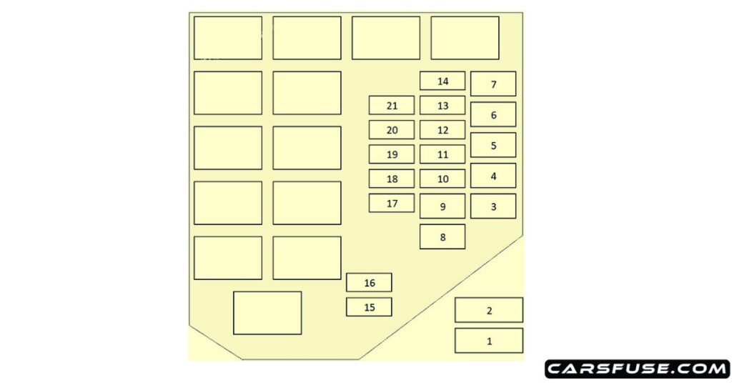
Engine Compartment

| Fuse Number | Fuse Amp. Rating | Protected Components |
|---|---|---|
| 1 | 60A | Fuses №16, 17, instrument panel fuses №1, 6, 11 |
| 2 | 100A | Fusible link № 1, 8, 9, fuse №10 (when engine stops); Fusible link №3, 4, 5, 6, fuses №12, 13, 14 (when engine starts) |
| 3 | 20A | INVECS-II 5A/T, TCL, engine control |
| 4 | 40A | Fuse №19, charging, headlamp |
| 5 | 30A | Full-auto air conditioner, cooling |
| 6 | 40A | Ignition switch |
| 7 | – | – |
| 8 | 50A | ABS |
| 9 | 30A | Instrument panel fuses №16, 17, power window |
| 10 | 30A | Condenser fan |
| 11 | – | – |
| 12 | 15A | Fog lamp |
| 13 | 10A | Turn-signal and hazard warning lamp |
| 14 | 15A | Stop lamp |
| 15 | 15A | Keyless entry receiver, motor antenna assembly, spare connector for radio |
| 16 | 10A | A/C-ECU power supply, TCL-ECU power supply, MUT-II power supply, engine-ECU power supply, key cylinder illumination lamp, keyless entry receiver, speedometer, trunk room lamp, clock, door-ajar indicator lamp, buzzer-ECU power supply, map lamp, motor antenna assembly, spare connector for radio |
| 17 | 10A | A/C compressor |
| 18 | 10A | High beam indicator lamp |
| 19 | 10A | Illumination lamp, tail lamp, position lamp, license plate lamp, buzzer-ECU |
| 20 | 20A | Headlamp (LH), fuse №18 (high beam indicator lamp) |
| 21 | 20A | Headlamp (RH) |
Next Post: 2021-2023 Mazda MX-30 EV Fuse Box Diagram
Tom Smith is a passionate car mechanic and automotive enthusiast, specializing in the intricate world of car fuse boxes. With years of hands-on experience under the hood, he has earned a reputation as a reliable expert in his field. As the founder and content creator of the popular blog website 'carsfuse.com,' Tom has dedicated himself to sharing his extensive knowledge of car fuse boxes and electrical systems with the world.

