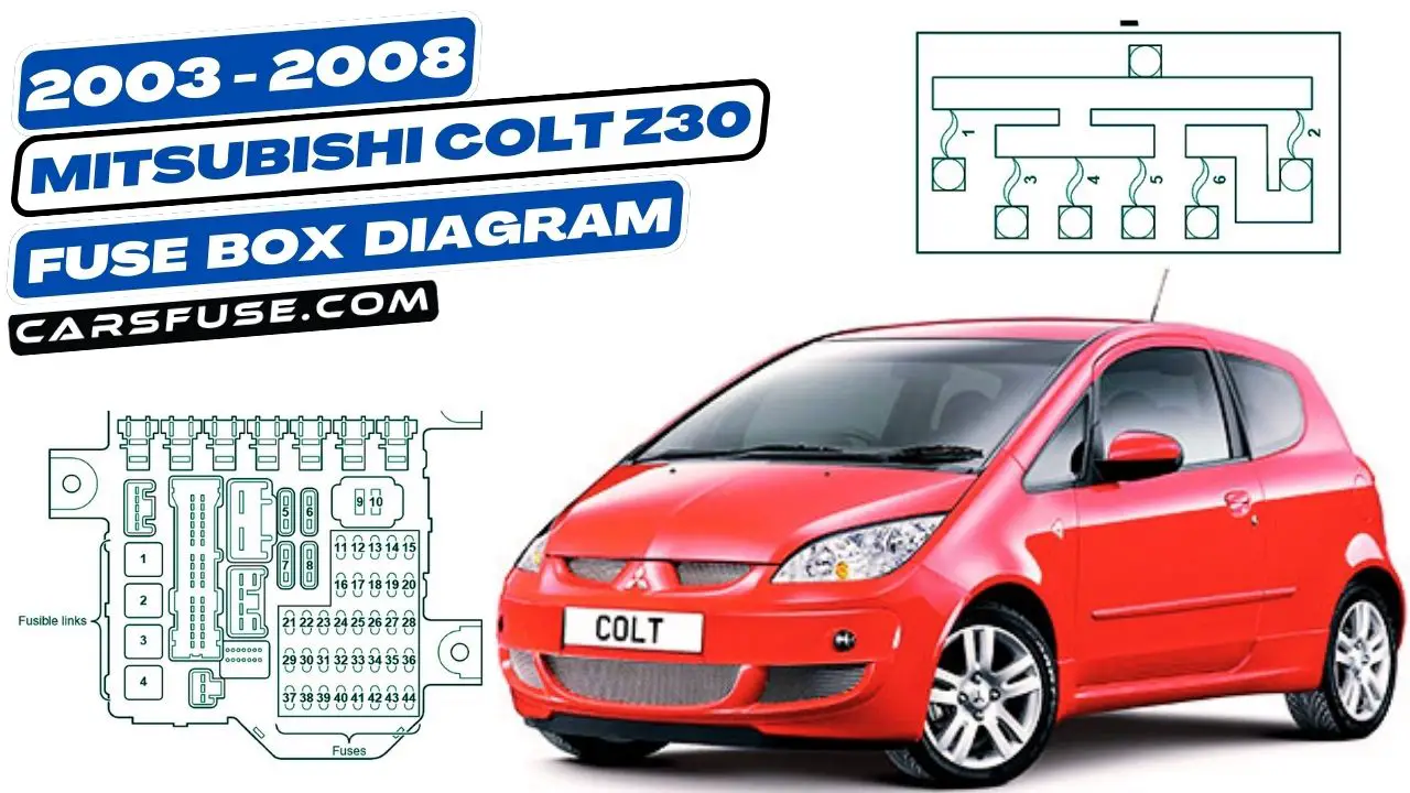
The Mitsubishi Colt Z30 is a popular car that is known for its reliability and fuel efficiency. However, even the best cars can experience electrical problems from time to time. If you are having trouble with an electrical component in your Colt Z30, one of the first things you should check is the fuse box.
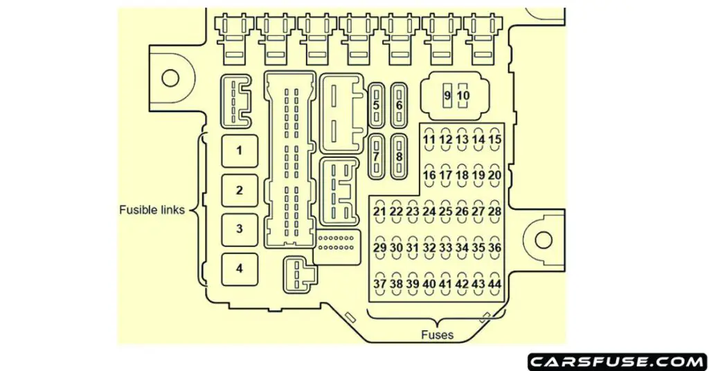
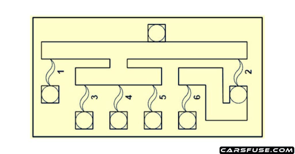
This article provides fuse box diagrams for the 2003-2008 Mitsubishi Colt Z30. The diagrams show the location, function, and rating of each fuse and relay. By following the information in this article, you can easily troubleshoot electrical problems in your Colt Z30.
The fuse box is a small box that contains fuses and relays. Fuses are responsible for protecting the electrical system from damage caused by overloads or short circuits. Relays are used to switch high-current circuits on and off.
The Colt Z30 has two fuse boxes: one in the engine bay and one in the passenger compartment. The engine bay fuse box contains fuses for the engine and other major components. The passenger compartment fuse box contains fuses for the interior lights, accessories, and other electronics.
Table of Contents
Instrument Panel

| Fuse Number | Fuse Amp. Rating | Load circuit |
|---|---|---|
| 1 | 40A | Ignition switch circuit |
| 2 | 40A | Power window main switch and power window sub switch |
| 3 | 40A | Cooling fan motor |
| 4 | – | – |
| 5 | 30A | Rear window defogger |
| 6 | – | – |
| 7 | – | – |
| 8 | 30A | ETACS-ECU, ignition key cylinder illumination lamp, luggage compartment lamp, and room lamp |
| 9 | 10A | ETACS-ECU, radio and CD player |
| 10 | 10A | ETACS-ECU, windshield wiper motor, and washer motor |
| 11 | 7.5A | – |
| 12 | 7.5A | Sunroof motor assembly |
| 13 | 20A | Fog lamp switch, hazard warning switch, position lamp, and tail lamp |
| 14 | 7.5A | Airflow sensor (4G15), camshaft position sensor, crank angle sensor, EGR valve (CVT), engine control relay, engine-CVT-ECU (CVT), engine-ECU (M/T), fuel pressure control solenoid valve (4G15), injector, oxygen sensor, primary speed sensor (CVT), purge control solenoid valve, oil feeder control valve, secondary speed sensor (CVT), turbine speed sensor (CVT), throttle valve control servo relay and wastegate solenoid valve (4G15) |
| 15 | 7.5A | License plate lamp, position lamp, and tail lamp |
| 16 | 20A | A/C compressor, A/C compressor relay, engine-CVT-ECU (CVT), and engine-ECU (M/T) |
| 17 | 15A | Fuel pump and gauge unit |
| 18 | 10A | Horn and horn relay |
| 19 | 10A | Headlamp (HI) |
| 20 | 10A | Headlamp (HI) |
| 21 | – | – |
| 22 | – | – |
| 23 | 7.5A | Door mirror assembly |
| 24 | 10A | ETACS-ECU, rear wiper motor, and washer motor |
| 25 | 15A | Cigarette lighter |
| 26 | 15A | Engine-CVT-ECU (CVT), SRS-ECU, and backup lamp |
| 27 | 20A | Sunroof motor assembly |
| 28 | – | – |
| 29 | 10A | – |
| 30 | 15A | – |
| 31 | 10A | ETACS-ECU and turn-signal lamp |
| 32 | 10A | – |
| 33 | 15A | CVT control solenoid valve assembly, CVT control relay, and engine-CVT-ECU (CVT) |
| 34 | 15A | Fog lamp and fog lamp relay |
| 35 | 15A | Headlamp (LO) |
| 36 | 15A | Headlamp (LO) |
| 37 | 7.5A | Diagnosis connector, ETACS-ECU, door lock actuator, and door mirror assembly |
| 38 | 7.5A | Engine-CVT-ECU (CVT), SRS-ECU, and back-up lamp |
| 39 | 10A | Ignition coil and noise condenser |
| 40 | 7.5A | ABS-ECU (4A91), ASC-ECU (4G15)>, column switch, combination meter, EPS-ECU, ETACS-ECU, SRS-ECU, G and yaw rate sensor and steering wheel sensor |
| 41 | 7.5A | Blower relay, combination meter, cooling fan control relay, engine-CVT-ECU (CVT), engine-ECU (M/T), outside/inside air selection damper control motor and rear window defogger relay |
| 42 | 15A | ABS-ECU (4A91), ASC-ECU (4G15), engine-CVT-ECU (CVT) engine-ECU (M/T), high-mounted stop lamp and stop lamp |
| 43 | 10A | Combination meter, blower motor, power transistor, and resistor |
| 44 | 20A | Column switch, combination meter, ETACS-ECU, engine-CVT-ECU (CVT), engine-ECU (M/T), key reminder switch, radio, and CD player |
Engine Compartment

| Fuse Number | Fuse Amp. Rating | Load circuit |
|---|---|---|
| 1 | 120A | ETACS-ECU, headlamp relay, fusible link №1, 2, 3 (in junction block) and fuse №10, 14, 15, 16, 17, 18, 19, 20, 31, 35, 36, 42, 43, 44 circuit |
| 2 | 120A | Fusible link №6 (in fusible link box) circuit/battery and fusible link №1,3, 4, 5 (in fusible link box) |
| 3 | 40A | ABS-ECU and ASC-ECU |
| 4 | 60A | EPS-ECU |
| 5 | 30A | ABS-ECU, ASC-ECU and alternator |
| 6 | 80A | Fuse №5, 8, 11, 24, 27, 29, 30, 33, 34 |
Next Post: 1994-1997 Acura Integra Fuse Box Diagram
Tom Smith is a passionate car mechanic and automotive enthusiast, specializing in the intricate world of car fuse boxes. With years of hands-on experience under the hood, he has earned a reputation as a reliable expert in his field. As the founder and content creator of the popular blog website 'carsfuse.com,' Tom has dedicated himself to sharing his extensive knowledge of car fuse boxes and electrical systems with the world.

