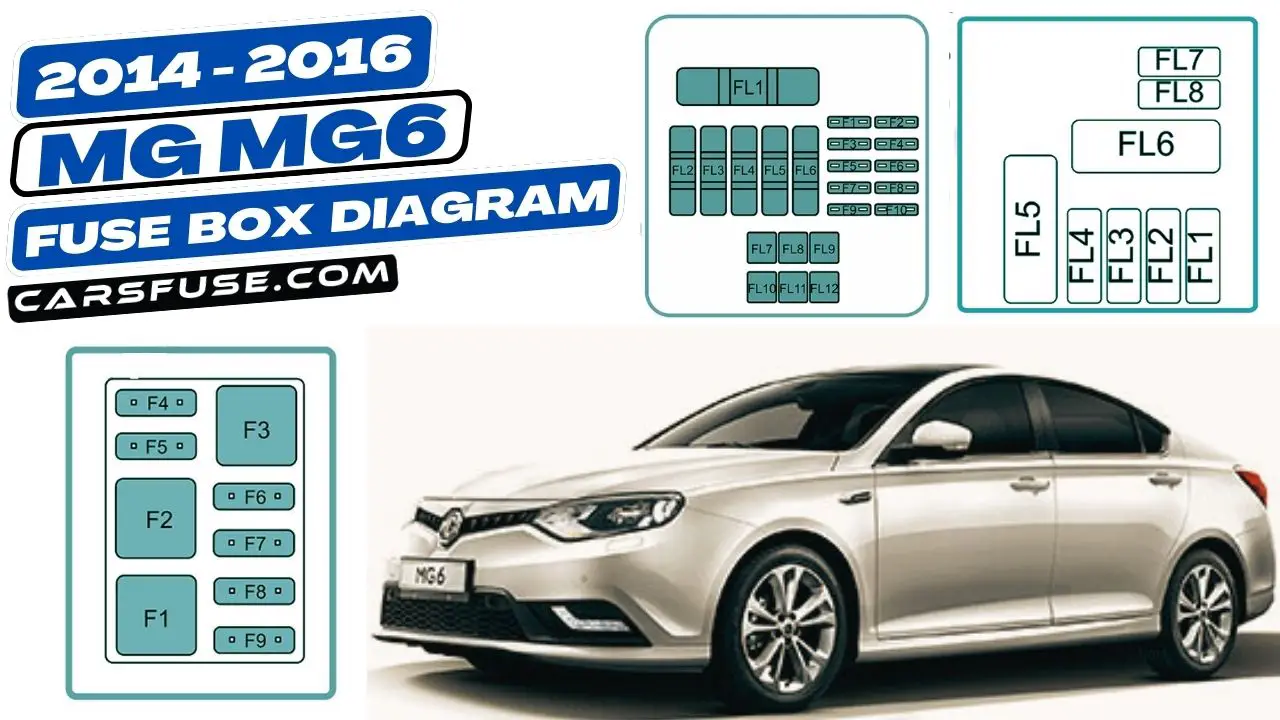
The MG MG6 is a mid-size sedan that was produced by MG Motor from 2010 to 2016. It was available in both petrol and diesel engine options and was sold in several countries around the world.
This article provides diagrams of the fuse boxes for the MG MG6 (2014-2016). The diagrams show the location of each fuse and relay, as well as the amperage rating for each fuse. This information can be used to troubleshoot electrical problems in the MG MG6.
Table of Contents
Fuse Box Location
The MG MG6 has two fuse boxes located in the car: one under the dashboard and one in the engine bay. The fuse box under the dashboard is responsible for the electrical circuits for the interior of the car, while the fuse box in the engine bay is responsible for the electrical circuits for the engine and other components under the hood.
Engine Compartment
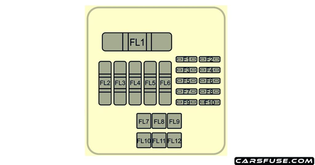
| Fuse Number | Fuse Amp. Rating | Protected Components |
|---|---|---|
| F1 | 15A | Sensor – Wide Band, Control Unit -Glow Plug, ECU – Engine, Switch – Clutch Pedal |
| F2 | 20A | Power Supply – Fuel Filter, Bypass -EGR Cooling, Actuator – Variable Swirl, Valve – Throttle Actuator, Sensor – Hot Film Airmass, Variable Geometry Turbo Controller |
| F3 | 10A | Pump – High Pressure, Valve – Pressure Control |
| F4 | 15A | Cooling Fan, Relay – Starter, Relay -Fuel Heater, Master Switch – Start Stop, Relay – Electric Water Heater 1, Relay – Electric Water Heater 3, Switch – Neutral, ECU – Engine |
| F5 | 10A | Spare |
| F6 | 15A | Day Running Lamps |
| F7 | 30A | Lamp – Direction Indicator Front – LH, Lamp – Direction Indicator Rear – LH, Lamp – Side Repeater – LH, Relay -Reverse Lamp, Relay – Position Lamp, Lamp – Rear Brake – LH , Passenger Compartment Fuses 3, 12, 36 |
| F8 | 20A | Passenger Compartment Fuse 7 |
| F9 | 10A | Relay – Compressor Clutch – Air Conditioning, Compressor – Air Conditioning Clutch |
| F10 | 30A | Relay – Wiper 1, Relay – Wiper 2 |
| FL1 | 200A | Alternator, Engine Compartment Fuse Links 2, 7,10 and Fuses 5, 8, 9 |
| FL2 | 60A | Passenger Compartment Fuses 1, 6, 9, 22, 24, 25, 27, 28, 42, Relay – Switched |
| FL3 | 50A | Relay – Horn, Rotary Coupler, Passenger Compartment Fuses 16, 17, 18 |
| FL4 | 50A | Cooling Fan |
| FL5 | I00A | Relay – Dipped Beam, Relay – Rear Fog Lamp, Passenger Compartment Fuses 19, 20, 21, 23, 30, 35, 37, 39, 40, 41, 43, 45, 46 |
| FL6 | 70A | EH PAS ECU & Pump |
| FL7 | 40A | Relay – Starter, Starter Motor |
| FL8 | 40A | SCS ECU (Pump) |
| FL9 | 50A | Passenger Compartment Fuses 2, 5, 10, 13, 14, 15, 26, 38, 44, Relay – Heated Rear Screen, Relay – Main Beam, Relay – Auxiliary |
| FL10 | 40A | Relay – Blower, Motor – Blower, A/C Control Panel |
| FL11 | 25A | SCS ECU (Valve) |
| FL12 | 50A | Relay – Dipped Beam, Lamp – Direction Indicator Front – RH, Lamp – Direction Indicator Rear – RH, Lamp – Side Repeater – RH, Lamps – Rear Brake -RH, Passenger Compartment Fuses 8, 31, 32 |
Auxiliary Fuse Box
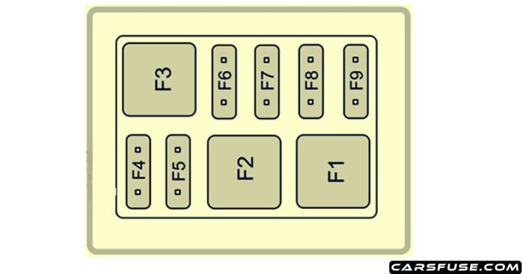
| Fuse Number | Fuse Amp. Rating | Protected Components |
|---|---|---|
| F1 | 30A | DC/DC Converter |
| F2 | 30A | Relay – Electric Water Heater 1, Electric Water Heater Element 1 |
| F3 | 30A | Headlamp Wash System |
| F4 | 20A | Relay – Fuel Heater, Fuel Heater |
| F5 | 20A | AFS System |
| F6 | 5A | Interior Lamp – Front, Interior Lamp -Rear, Lamp – Vanity Mirrors |
| F7 | 15A | Entertainment System |
| F8 | 10A | A/C Control Panel, Fresh/Recycle Motor |
| F9 | 10A | Instrument Pack |
Battery Top Fuse Box
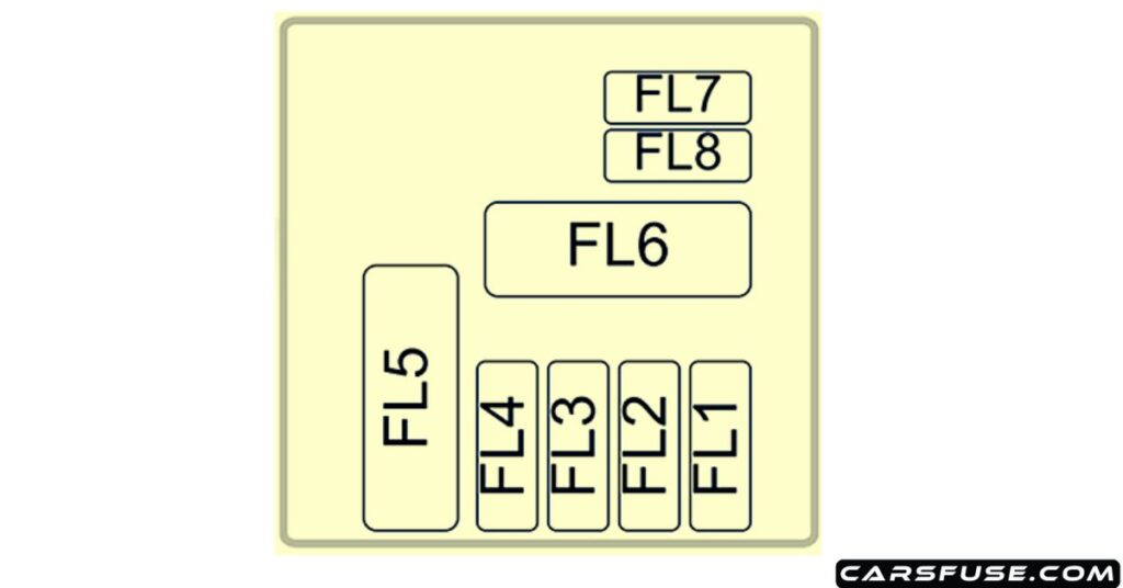
| Fuse Number | Fuse Amp. Rating | Protected Components |
|---|---|---|
| FL1 | 30A | EPB ECU |
| FL2 | 30A | EPB ECU |
| FL3 | 125A | Auxiliary Fuses 1, 2, 3, 4, 5, Relay – Electric Water Heater 2, Electric Water Heater Element 2 |
| FL4 | 60A | Control Unit Glow Plug |
| FL5 | – | – |
| FL6 | 450A | Motor – Starter |
| FL7 | 5A | EBS |
| FL8 | 30A | Relay – Electric Water Heater 3, Electric Water Heater Element 3 |
Passenger Compartment
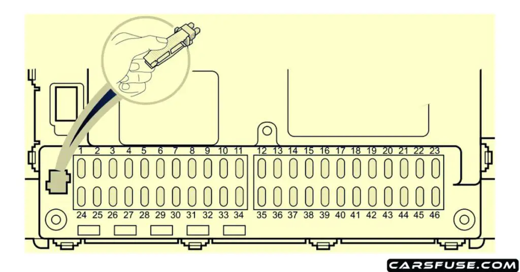
| Fuse Number | Fuse Amp. Rating | Protected Components |
|---|---|---|
| F1 | 15A | Spare |
| F2 | 15A | Front Power Socket |
| F3 | 10A | Reverse Lamps, Interior Mirror, Camera |
| F4 | 15A | Spare |
| F5 | 5A | Heated Mirror |
| F6 | 10A | Inertia Switch |
| F7 | 15A | Rear Accessory Socket |
| F8 | 30A | Power Supply – Window Lift Front – LH |
| F9 | 5A | Switch – Reverse Lamps, Switch – Master Light, Motor – Headlamp Levelling, AFS System, Passenger Airbag ON/OFF Indicator |
| F10 | 20A | Headlamp Main Beams |
| F11 | – | – |
| F12 | 5A | Side Lamp – LH, Tail Lamp – LH, Rear Number Plate Lamps |
| F13 | 5A | Switch – EPB |
| F14 | 5A | Switch – Steering Wheel Remote |
| F15 | 20A | ESCL ECU |
| F16 | 30A | Pump – Windscreen Wash |
| F17 | 30A | Power Supply – Passenger Seat |
| F18 | 15A | Horns |
| F19 | 30A | Heated Seat – Front |
| F20 | 20A | Headlamp Dipped Beam – RH |
| F21 | 30A | Power Supply – Driver Seat |
| F22 | 5A | A/C Control Panel, Heated Seat – Front |
| F23 | 30A | Power Supply – Window Lift Rear – LH |
| F24 | 30A | Power Supply – Window Lift Front – RH |
| F25 | 15A | Spare |
| F26 | 25A | Heater Rear Window |
| F27 | 5A | Switch – Ignition |
| F28 | 5A | Spare |
| F29 | 15A | Spare |
| F30 | 15A | Spare |
| F31 | 25A | Passenger Door Locks, Rear Door Locks |
| F32 | 20A | Headlamp Dipped Beam – LH |
| F33 | – | – |
| F34 | – | – |
| F35 | 10A | Spare |
| F36 | 5A | Side Lamp – RH, Tail Lamp – RH |
| F37 | 5A | Diagnostic Socket |
| F38 | 5A | Lamp – Glovebox |
| F39 | 10A | Driver Door Locks, Motor – Fuel Flap Release, Tailgate Release Motor Relay, Motor – Tailgate Release |
| F40 | 15A | Spare |
| F41 | 10A | Rear Fog Lamps |
| F42 | 10A | Airbag ECU |
| F43 | 20A | Spare |
| F44 | 5A | Interior Mirror, Rain Sensor, PDC ECU |
| F45 | 10A | Multifunction Control Switch, Master Light Switch, Driver Door Switch Pack, Navigation Display Power |
| F46 | 30A | Power Supply – Window Lift Rear – RH |
Next Post: 1995-1999 Mitsubishi Eclipse Fuse Box Diagram
Tom Smith is a passionate car mechanic and automotive enthusiast, specializing in the intricate world of car fuse boxes. With years of hands-on experience under the hood, he has earned a reputation as a reliable expert in his field. As the founder and content creator of the popular blog website 'carsfuse.com,' Tom has dedicated himself to sharing his extensive knowledge of car fuse boxes and electrical systems with the world.

