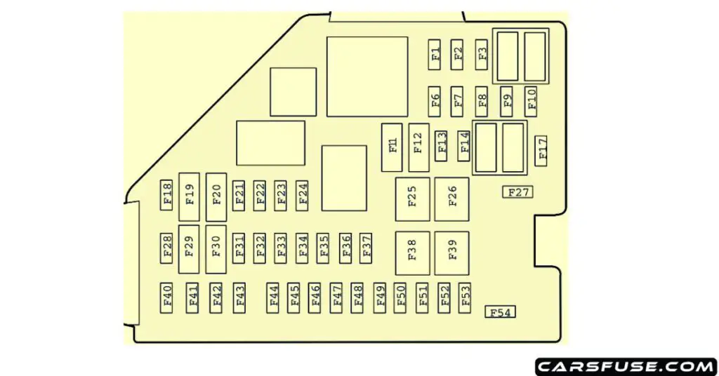
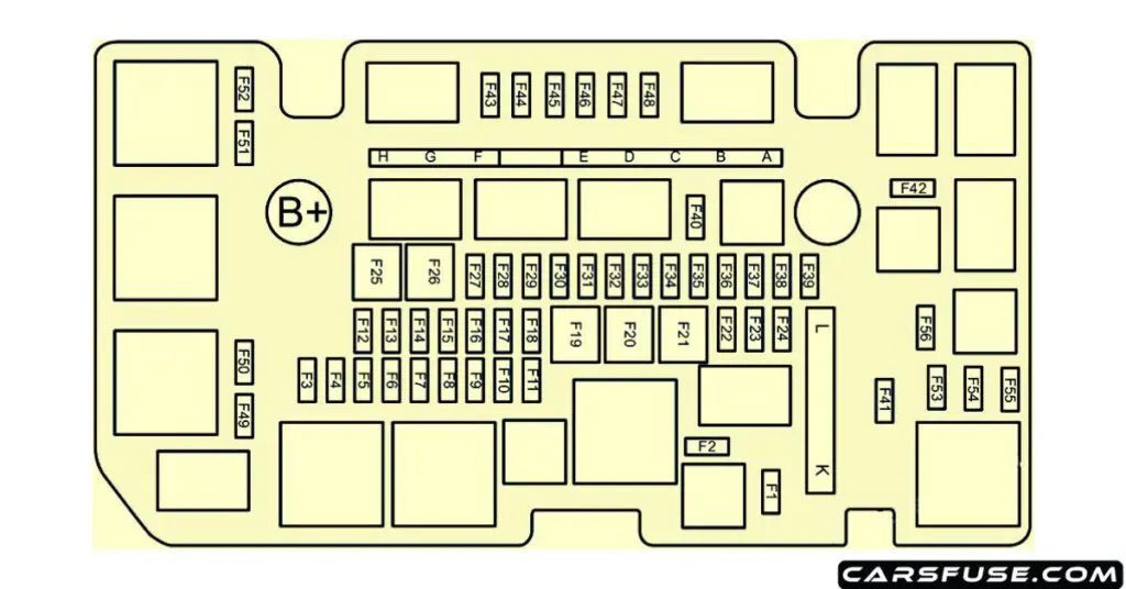
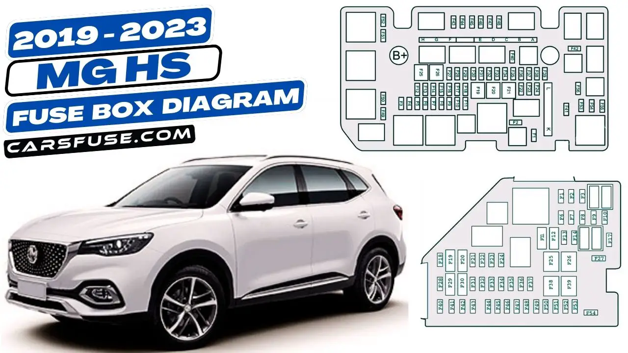
This blog post will provide you with the fuse box diagram for the MG HS, which was manufactured between 2019 and 2023. The fuse box diagram is a helpful tool for identifying and troubleshooting electrical problems in your car. By understanding where the fuses are located and what they do, you can quickly and easily diagnose any problems that may arise.
By the end of this blog post, you will have a complete understanding of the fuse box diagram for your car and be able to use it to troubleshoot any electrical problems that may arise.
Table of Contents
Fuse Box Location
The fuse box on an MG HS is located in two different places:
- Passenger compartment fuse box: This fuse box is located under the lower dash panel, to the left of the steering column.
- Engine compartment fuse box: This fuse box is located in the engine compartment, on the passenger side of the car.
Passenger Compartment

| Fuse Number | Fuse Amp. Rating | Protected Components |
|---|---|---|
| F1 | 10A | Supplemental Restraint System Sensing and Diagnostic Module, DC-DC Converter, Communication Module, Shifter Control Unit, Instrument Pack, Body Control Module, SDM Auxiliary Display Module |
| F2 | 7.5A | Transmission Control Module, Reverse Lamp Switch, Engine Control Module |
| F3 | 5A | Front View Camera Module, Forward Detection Radar |
| F6-F7 | – | – |
| F8 | 15A | Front Console Power Socket |
| F9 | 5A | USB Charging Port |
| F10 | – | – |
| F11 | 7.5A | Heated Exterior Rearview Mirror |
| F12 | 25A | Heated Rear Window |
| F13-F14 | – | – |
| F17 | – | – |
| F18 | 30A | Rear Left Window Regulator |
| F19 | 5A | EPB Switch, Gear Display |
| F20 | 30A | Rear Right Window Regulator |
| F21 | 10A | Front Right Seat Heater Relay |
| F22 | 5A | Data Link Connector |
| F23 | 10A | Heated Front Left Seat |
| F24 | 10A | Gateway |
| F25 | 30A | KLR Relay |
| F26 | 30A | Passenger Window Regulator |
| F27 | – | – |
| F28 | 5A | PEPS Control Unit, Spare Coil |
| F29 | 10A | Gateway |
| F30 | 5A | Driver Window Combination Switch, Rain/Light Sensor |
| F31 | – | – |
| F32 | 5A | Atmosphere Lamp Control Module |
| F33 | 5A | Supplemental Restraint System Sensing and Diagnostic Module |
| F34 | 5A | Communication Module |
| F35 | 10A | Digital Audio Broadcasting (DAB) Module |
| F36 | 10A | Electronic Steering Column Lock Control Module |
| F37 | 20A | Driver Power Seat Adjustment |
| F38 | 30A | Driver Window Regulator |
| F39 | 30A | Blower |
| F40 | 15A | Entertainment System |
| F41 | 5A | Upper Centre Console Switch |
| F42 | 10A | HVAC Control Module |
| F43 | 5A | Instrument Pack |
| F44 | 5A | Rear Driving Assist System |
| F45 | 30A | Sunroof Motor |
| F46 | 5A | Tyre Pressure Monitoring System |
| F47 | 30A | Sunshade Motor |
| F48 | 20A | Front Passenger Power Seat Adjustment |
| F49 | 30A | Power Liftgate Control Module |
| F50 | – | – |
| F51 | 30A | Rear Window/Exterior Rearview Mirror Heater Relay |
| F52 | 10A | KL15 Switch Relay |
| F53 | 20A | Shifter Control Unit |
| F54 | – | – |
Engine Compartment

| Fuse Number | Fuse Amp. Rating | Protected Components |
|---|---|---|
| F1 | – | – |
| F2 | – | – |
| F3 | 10A | Front Fog Lamp |
| F4 | 25A | Body Control Module |
| F5 | 25A | Body Control Module |
| F6 | – | – |
| F7 | 10A | Engine Control Module |
| F8 | – | – |
| F9 | 15A | Horn |
| F10 | 5A | Transmission Gear Shift Actuator |
| F11 | – | – |
| F12 | 25A | Body Control Module |
| F13 | 25A | Body Control Module |
| F14-F19 | – | – |
| F20 | 30A | DC-DC Converter |
| F21 | 30A | DC-DC Converter |
| F22-F23 | – | – |
| F24 | 15A | Rear Wiper Relay |
| F25 | 30A | DC-DC Converter |
| F26 | 25A | Body Control Module |
| F27 | 10A | Windscreen/Rear Window Washer Relay |
| F28 | 25A | Super Lock Relay |
| F29 | 25A | Body Control Module |
| F30 | 25A | Front Wiper Relay |
| F31-F35 | – | – |
| F36 | 10A | A/C Compressor Relay |
| F37 | – | – |
| F38 | 15A | Fuel Pump Relay |
| F39 | 5A | Crank Signal |
| F40-F42 | – | – |
| F43 | 5A | DC-DC Converter Relay, Fuel Pump Relay, A/C Compressor Relay, Clutch Position Sensor, Brake Pedal Switch, Neutral Position Sensor, Cooling Fan Relay Box |
| F44 | 15A | Electronic Thermostat, WT Valve – Intake, WT Valve – Exhaust, Upstream Oxygen Sensor, Downstream Oxygen Sensor, Canister Shut off Valve |
| F45 | 10A | Engine Oil Control Valve, Canister Control Valve, Exhaust Gas Control Valve, Relief Valve |
| F46 | 15A | Engine Control Module |
| F47 | 15A | Ignition Coil, Air Flow Sensor |
| F48 | – | – |
| F49 | 10A | Right Headlamp |
| F50 | 10A | Left Headlamp |
| F51-F56 | – | – |
| MF1 A | 80A | Electric Power Steering Control Module |
| MF1 B | 40A | 7-speed Dual Clutch Transmission Control Module Relay |
| MF1 C | 40A | Dynamic Stability Control System (pump) |
| MF1 D | 40A | Dynamic Stability Control System (valve) |
| MF1 E | – | – |
| MF1 F | 30A | Starter Relay |
| MF1 G | – | – |
| MF1 H | 50A | Cooling Fan |
| MF2 K | 100A | Passenger Compartment Fuse Box |
| MF2 L | 30A | Electric Vacuum Pump |
Next Post: 2013-2018 MG MG3 Fuse Box Diagram
Tom Smith is a passionate car mechanic and automotive enthusiast, specializing in the intricate world of car fuse boxes. With years of hands-on experience under the hood, he has earned a reputation as a reliable expert in his field. As the founder and content creator of the popular blog website 'carsfuse.com,' Tom has dedicated himself to sharing his extensive knowledge of car fuse boxes and electrical systems with the world.

