The Acura TL UA6/UA7 is a mid-size luxury sedan that was produced from 2004 to 2008. It is powered by a 3.2L V6 engine and comes standard with front-wheel drive. The TL is known for its comfortable ride, powerful engine, and stylish interior.
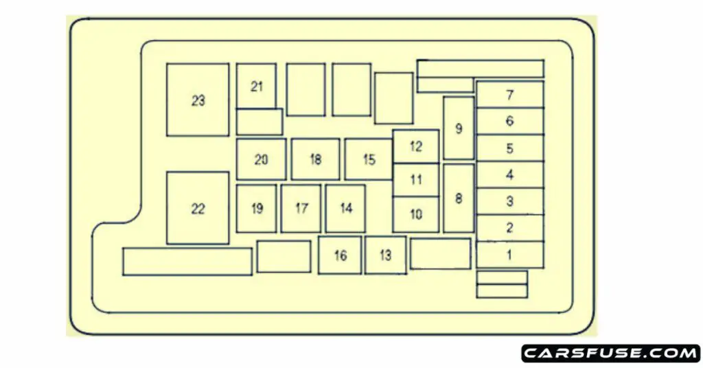
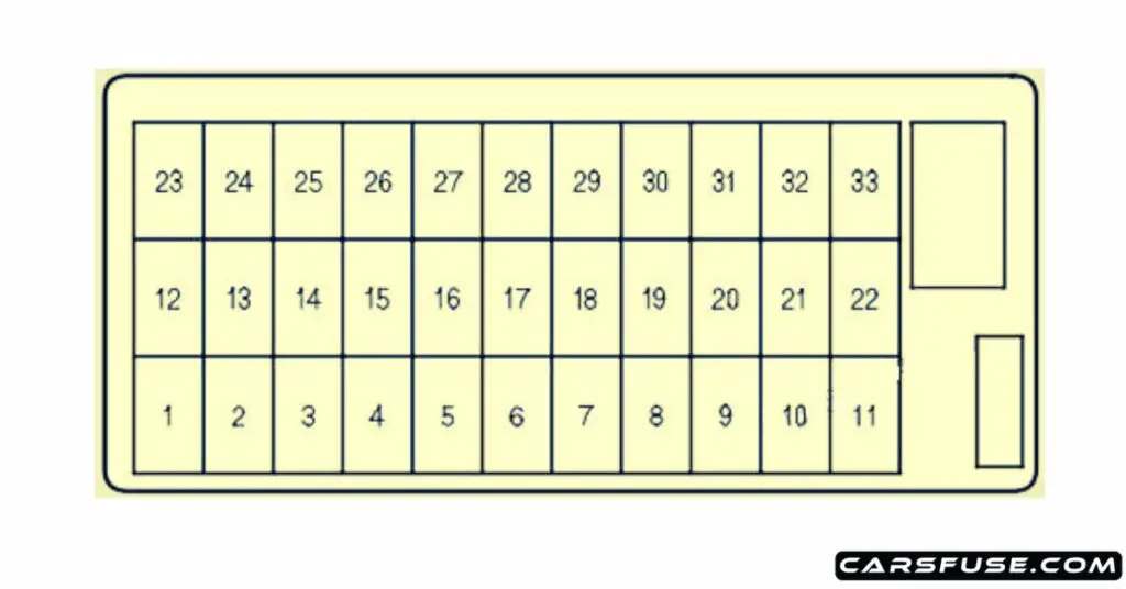
The fuse box diagram can be helpful if you need to replace a blown fuse or relay in your Acura TL UA6/UA7. By knowing the location and function of each fuse and relay, you can quickly and easily identify the fuse or relay that needs to be replaced.
This blog post will provide a fuse box diagram for the Acura TL UA6/UA7. The fuse box diagram will show the location of each fuse and relay in the fuse box, as well as the function of each fuse and relay.
Table of Contents
Fuse box location
- The interior fuse box is on the driver’s lower left side. To remove the fuse box lid, put your finger in the notch on the lid, pull it toward you, and take it out of its hinges.
- The under-hood fuse box is on the driver’s side next to the air cleaner housing.
Cigar lighter / power outlet fuse in the Acura TL is the fuse No.9 in the passenger compartment fuse box.
[2004/2005/2006]
Engine Compartment

| Fuses Number | Fuses Amp. Rating | Protected Components |
|---|---|---|
| 1 | 15 A | Left Headlight Low Beam |
| 2 | 30 A | Rear Defroster Coil |
| 3 | 7.5 A | Left Headlight High Beam |
| 4 | 10 A | Small Light |
| 5 | 7.5 A | Right Headlight High Beam |
| 6 | 15 A | Right Headlight Low Beam |
| 7 | 7.5 A | Back Up |
| 8 | 15 A | IGP |
| 9 | 30 A | Condenser Fan |
| 10 | 20 A | Front Fog Light (U.S. models) |
| 10 | 15 A | Daytime Running Light (Canadian models) |
| 11 | 30 A | Radiator Fan Motor |
| 12 | 7.5 A | MG Clutch Relay |
| 13 | 20 A | Horn, Stop |
| 14 | 40 A | Rear Defroster |
| 15 | 40 A | Back UP, ACC |
| 16 | 15 A | Hazard Warning |
| 17 | 30 A | VSA Pump Motor Relay |
| 18 | 40 A | VSA Fail Safe Relay |
| 19 | 40 A | FI ECU (ECM/PCM) |
| 20 | 40 A | Power Seat |
| 21 | 40 A | Heater Motor |
| 22 | 120 A | Battery |
| 23 | 50 A | IGI Main |
Passenger Compartment

| Fuses Number | Fuses Amp. Rating | Protected Components |
|---|---|---|
| 1 | 15 A | DBW |
| 2 | 15 A | IG1 Coil |
| 3 | — | Not Used |
| 4 | 15 A | LAF |
| 5 | 20 A | Radio |
| 6 | 7.5 A | Interior Lights |
| 7 | 7.5 A | Back Up |
| 8 | 20 A | Door Lock |
| 9 | 15 A | Accessory Socket |
| 10 | 7.5 A | IG1 OPDS |
| 11 | 30 A | IG1 Wiper |
| 12 | 7.5 A | TPMS |
| 13 | 20 A | Passenger’s Power Seat (Recline) |
| 14 | 20 A | Driver’s Power Seat (Slide) |
| 15 | 20 A | Seat Heater |
| 16 | 20 A | Driver’s Power Seat (Recline) |
| 17 | 20 A | Passenger’s Power Seat (Slide) |
| 18 | 15 A | IG1 ACG |
| 19 | 15 A | IG1 Fuel Pump |
| 20 | 15 A | Washer |
| 21 | 7.5 A | Meter |
| 22 | 10 A | SRS |
| 23 | 7.5 A | IGP |
| 24 | 20 A | Rear Left Power Window |
| 25 | 20 A | Rear Right Power Window |
| 26 | 30 A | Front Right Power Window |
| 27 | 30 A | Front Left Power Window |
| 28 | 20 A | Moonroof |
| 29 | 7.5 A | VBSOL |
| 30 | 7.5 A | HAC |
| 31 | 7.5 A | OP2 |
| 32 | 7.5 A | ACC |
| 33 | 7.5 A | HAC OP |
[2007/2008]
Engine Compartment

| Fuses Number | Fuses Amp. Rating | Protected Components |
|---|---|---|
| 1 | 15 A | Left Headlight Low Beam |
| 2 | 30 A | Rear Defroster Coil |
| 3 | 7.5 A | Left Headlight High Beam |
| 4 | 10 A | Small Light |
| 5 | 7.5 A | Right Headlight High Beam |
| 6 | 15 A | Right Headlight Low Beam |
| 7 | 7.5 A | Back Up |
| 8 | 15 A | FI ECU |
| 9 | 30 A | Condenser Fan |
| 10 | 10 A | Fog Light |
| 11 | 30 A | Radiator Fan Motor |
| 12 | 7.5 A | MG Clutch Relay |
| 13 | 20 A | Horn, Stop |
| 14 | 40 A | Rear Defroster |
| 15 | 40 A | Back UP, ACC |
| 16 | 15 A | Hazard Warning |
| 17 | 30 A | VSA Pump Motor Relay |
| 18 | 40 A | VSA Fail Safe Relay |
| 19 | 40 A | FI ECU (ECM/PCM) |
| 20 | 40 A | Power Seat |
| 21 | 40 A | Heater Motor |
| 22 | 120 A | Battery |
| 23 | 50 A | IGI Main |
Passenger Compartment

| Fuses Number | Fuses Amp. Rating | Protected Components |
|---|---|---|
| 1 | 15 A | DBW |
| 2 | 15 A | IG1 Coil |
| 3 | 15 A | Daytime Running Light |
| 4 | 15 A | LAF |
| 5 | 20 A | Radio |
| 6 | 7.5 A | Interior Lights |
| 7 | 7.5 A | Back Up |
| 8 | 20 A | Door Lock |
| 9 | 15 A | Accessory Socket |
| 10 | 7.5 A | IG1 OPDS |
| 11 | 30 A | IG1 Wiper |
| 12 | 7.5 A | TPMS |
| 13 | 20 A | Passenger’s Power Seat (Recline) |
| 14 | 20 A | Driver’s Power Seat (Slide) |
| 15 | 20 A | Seat Heater |
| 16 | 20 A | Driver’s Power Seat (Recline) |
| 17 | 20 A | Passenger’s Power Seat (Slide) |
| 18 | 15 A | IG1 ACG |
| 19 | 15 A | IG1 Fuel Pump |
| 20 | 15 A | Washer |
| 21 | 7.5 A | Meter |
| 22 | 10 A | SRS |
| 23 | 7.5 A | IGP |
| 24 | 20 A | Rear Left Power Window |
| 25 | 20 A | Rear Right Power Window |
| 26 | 30 A | Front Right Power Window |
| 27 | 30 A | Front Left Power Window |
| 28 | 20 A | Moonroof |
| 29 | 7.5 A | VBSOL |
| 30 | 7.5 A | HAC |
| 31 | 7.5 A | OP2 |
| 32 | 7.5 A | ACC |
| 33 | 7.5 A | HAC OP |
Next Post: 2010-2012 Saab 9-5 Fuse Box Diagram
Tom Smith is a passionate car mechanic and automotive enthusiast, specializing in the intricate world of car fuse boxes. With years of hands-on experience under the hood, he has earned a reputation as a reliable expert in his field. As the founder and content creator of the popular blog website 'carsfuse.com,' Tom has dedicated himself to sharing his extensive knowledge of car fuse boxes and electrical systems with the world.

