The 2020–2023 Ford F-250, F-350, F-450, and F-550 Super Duty trucks feature advanced electrical systems designed to handle heavy workloads and modern technology. Each model includes multiple fuse boxes that protect the vehicle’s electrical circuits from overload or short circuits.
This guide provides detailed fuse box diagrams and descriptions for the Power Distribution Box and the Passenger Compartment Fuse Panel, helping you easily locate, identify, and replace fuses or relays for various electrical components in your Ford Super Duty.
Table of Contents
2020-2022 Ford F-250/F-350/F-450/F-550 Fuse Box Diagram
The 2020–2022 Ford F-250, F-350, F-450, and F-550 Super Duty trucks have two fuse box layouts: the Engine Compartment Fuse Box (under the hood) and the Passenger Compartment Fuse Panel (inside the cabin).
Engine Compartment Fuse Box
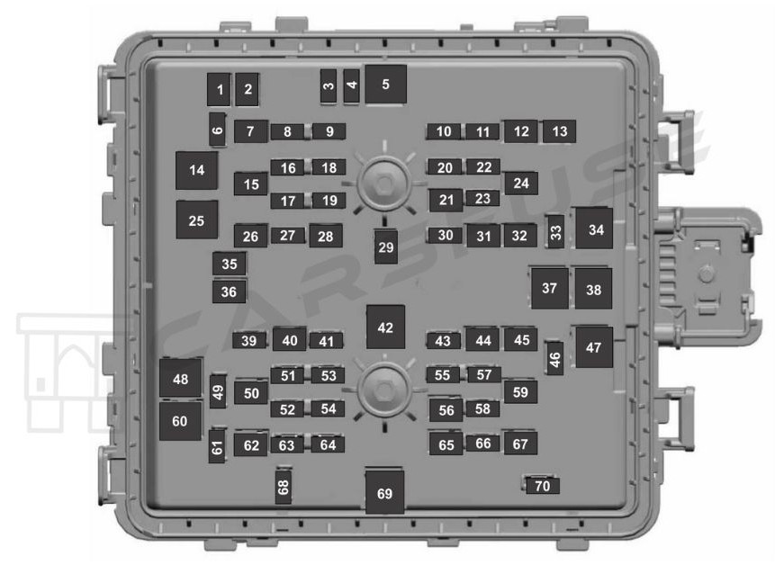
| Fuse Number | Fuse Rating | Protected Component |
|---|---|---|
| 1 | 20 A | Power point 4. |
| 2 | 20 A | Power point 3. |
| 3 | 10 A | Spot light module. |
| 4 | 10 A | Four-wheel drive vacuum solenoid. |
| 5 | 40 A | Active front steering. |
| 6 | 10 A | Snow plow. |
| 7 | 30 A | Trailer tow battery charge. |
| 8 | 10 A | Anti-lock brake system module. |
| 9 | 10 A | Electronic power assisted steering module. |
| 10 | 30 A | Trailer tow park lamps. |
| 11 | 20 A | Horn. |
| 12 | 30 A | Torque overlay. |
| 13 | 30 A | Power sliding rear window. |
| 14 | 40 A | Body control module – battery power in feed 1. |
| 15 | 30 A | Passenger seat power. |
| 16 | 10 A | Powertrain control module. Transmission control module. |
| 17 | 10 A | Blind spot information system. |
| 18 | 10 A | Four-wheel drive module. |
| 19 | 5 A | Adaptive cruise control. |
| 20 | 15 A | Heated mirrors. |
| 21 | 40 A | Heated rear window. |
| 22 | 10 A | On-board diagnostic module. Smart data link connector. |
| 23 | 15 A | Transmission control module. |
| 24 | 30 A | Driver power seat. |
| 25 | 25 A | Voltage quality module. |
| 26 | 30 A | Trailer tow battery charge. |
| 27 | 20 A | Rear heated seats. |
| 28 | 25 A | Glow plug (diesel). |
| — | Not used (gas). | |
| 29 | 40 A | Electric power assisted steering motor. |
| 30 | 10 A | Heated wiper park. |
| 31 | 20 A | Power point 5. |
| 32 | 25 A | Four-wheel drive module. |
| 33 | 10 A | Alternator sense line 2. |
| 34 | 50 A | Electric cooling fan (gas). Supplemental air heater (diesel). |
| 35 | 20 A | Power point 2. |
| 36 | 20 A | Power point 1. |
| 37 | 60 A | Anti-lock brake system pump. |
| 38 | 60 A | Inverter. |
| 39 | 25 A | Four-wheel drive module. |
| 40 | 30 A | Starter motor solenoid. |
| 41 | 10 A | Tailgate release solenoid. |
| 42 | 40 A | Blower motor. |
| 43 | 10 A | Trailer tow backup lamps. |
| 44 | 40 A | Trailer tow lighting module. |
| 45 | 30 A | Anti-lock brake system valve. |
| 46 | 30 A | Compressed natural gas module power. |
| 47 | 50 A | Supplemental air heater (diesel). |
| — | Not used (gas). | |
| 48 | 50 A | Supplemental air heater (diesel). |
| — | Not used (gas). | |
| 49 | — | Not used. |
| 50 | 30 A | Heated and cooled seats. |
| 51 | 20 A | Powertrain control module. |
| 52 | 15 A | Compressed natural gas (gas). Fuel rail pressure relief control (diesel). |
| 53 | 20 A | Exhaust gas recirculation stepper motor (gas). Universal exhaust gas oxygen sensors (gas). Exhaust gas recirculation cooler bypass (diesel). Urea pump motor controller (diesel). Oxygen sensors. |
| 54 | 20 A | A/C clutch relay power. Fan clutch. |
| 55 | 5 A | Rain sensor. |
| 56 | 30 A | Windshield wipers. |
| 57 | 10 A | Upfitter interface module. |
| 58 | 10 A | Alternator sense line. |
| 59 | 30 A | Power running boards. |
| 60 | 40 A | Body control module – battery power in feed 2. |
| 61 | 10 A | Telescopic mirror motors. |
| 62 | 40 A | Trailer brake control. Aftermarket e-brake access. |
| 63 | 15 A | Multi-contour seats. |
| 64 | 20 A | Ignition coil (gas). Glow plug module (diesel). Nitrogen oxide module (diesel). Urea level and quality sensor (diesel). |
| 65 | 30 A | Fuel pump. |
| 66 | 10 A | A/C clutch solenoid. |
| 67 | 40 A | Auxiliary lighting module. |
| 68 | 10 A | Powertrain control module. |
| 69 | 60 A | Body control module power. |
| 70 | 30 A | Trailer tow stop and turn lamps. |
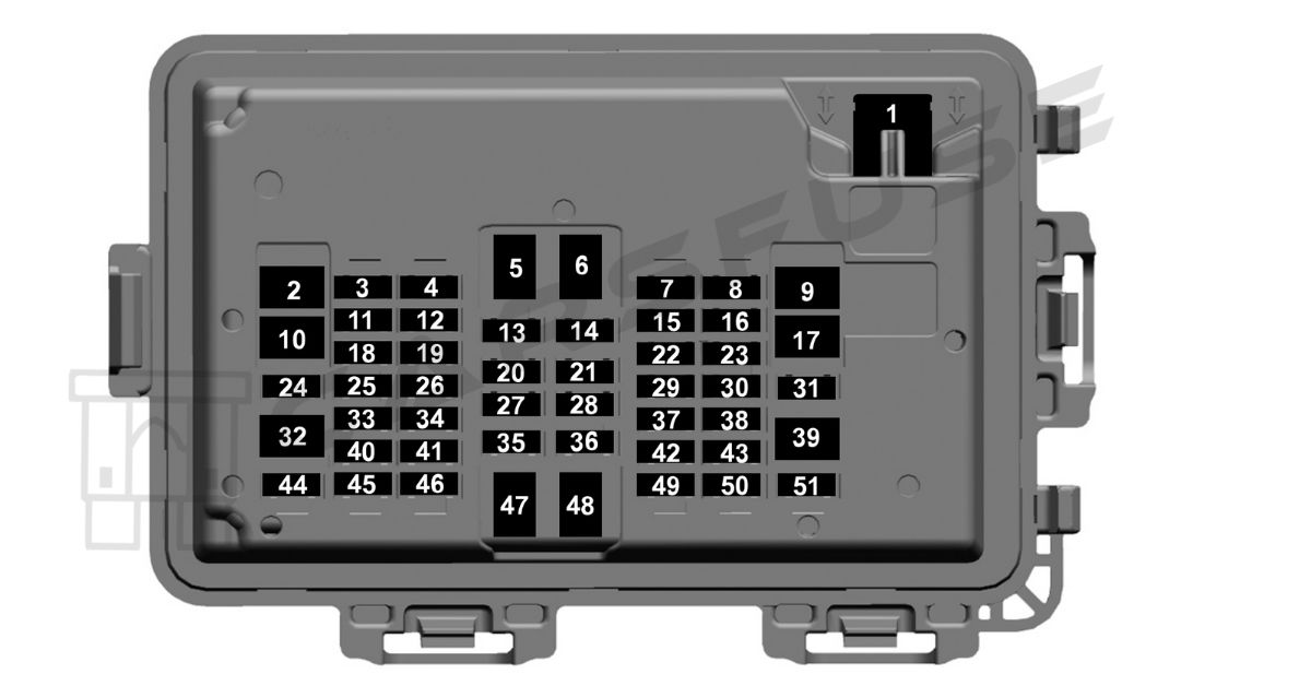
Passenger Compartment Fuse Panel
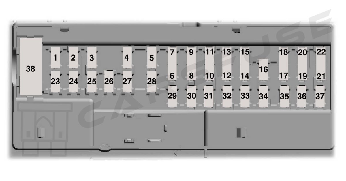
| Fuse Number | Fuse Rating | Protected Component |
|---|---|---|
| 1 | — | Not used. |
| 2 | 10 A | Driver door pack switch. Power sliding rear window switch. |
| 3 | 7.5 A | Seat memory switch. Power lumbar motor. Wireless charging module. |
| 4 | — | Not used. |
| 5 | — | Not used. |
| 6 | 10 A | Power telescoping mirrors switch. Front power windows switch. |
| 7 | 10 A | Brake on-off switch. |
| 8 | 5 A | Embedded modem. |
| 9 | 5 A | Combined sensor module. |
| 10 | — | Not used. |
| 11 | — | Not used. |
| 12 | 7.5 A | On-board diagnostic module. Smart data link connector. Climate control module. |
| 13 | 7.5 A | Steering column control module. Instrument cluster. |
| 14 | — | Not used. |
| 15 | 15 A | SYNC. Display. |
| 16 | — | Not used. |
| 17 | 7.5 A | Active front steering module. Park aid module. |
| 18 | 7.5 A | Selectable drive modes switch. Select shift switch. |
| 19 | 5 A | Head up display. |
| 20 | 5 A | Ignition switch. Key inhibit solenoid. |
| 21 | 5 A | Head up display. In-vehicle temperature and humidity sensor. |
| 22 | 5 A | Upfitter switches. |
| 23 | 30 A | Driver front door module. |
| 24 | 30 A | Moonroof. |
| 25 | — | Not used. |
| 26 | 30 A | Passenger front door module. |
| 27 | — | Not used. |
| 28 | 30 A | Amplifier. |
| 29 | 15 A | Adjustable pedals switch. |
| 30 | 5 A | Brake on-off output to trailer brake controller and customer access circuits. |
| 31 | 10 A | Remote keyless entry. |
| 32 | 20 A | Radio. |
| 33 | — | Not used. |
| 34 | 30 A | Run/start relay. |
| 35 | — | Not used. |
| 36 | 15 A | Camera module. Lane keeping system. Auto-dimming interior mirror. Rear heated seats. |
| 37 | 20 A | Heated steering wheel. |
| 38 | 30 A | Power windows. |
2023 Ford F-250/F-350/F-450/F-550 Fuse Box Diagram
The 2023 Ford F-250, F-350, F-450, and F-550 Super Duty trucks have two fuse box layouts: the Under Hood Fuse Box and the Interior Fuse Box (inside the cabin).
Engine Compartment Fuse Box
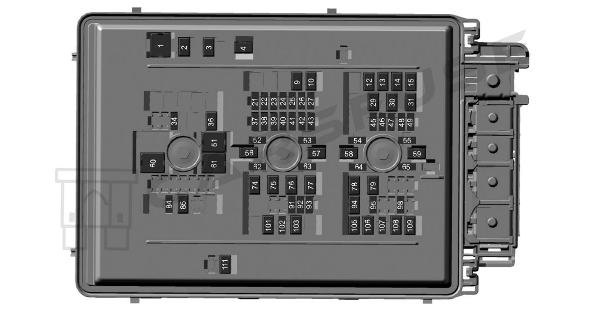
| Item | Rating | Protected Component |
|---|---|---|
| 1 | 50 A | Cooling fan 1. |
| 2 | 50 A | Heater. |
| 3 | 50 A | Heater. |
| 4 | 50 A | Heater. |
| 9 | 30 A | Four-wheel drive module. |
| 10 | 30 A | Compressed natural gas module switch. |
| 12 | 60 A | Anti-lock brake system pump. |
| 13 | 30 A | Passenger power seat. |
| 14 | 40 A | Anti-lock brake system valve. |
| 15 | 30 A | Body control module RP2 bus. |
| 21 | 10 A | Trailer tow backup lamps. |
| 22 | 10 A | Four-wheel drive system. |
| 23 | 20 A | Vehicle power 1. |
| 24 | 20 A | Vehicle power 2 (gas). |
| 10 A | Vehicle power 2 (diesel). | |
| 25 | 15 A | Vehicle power 3 (gas). |
| 10 A | Vehicle power 3 (diesel). | |
| 26 | 20 A | Vehicle power 4. |
| 27 | 10 A | Vehicle power 5 (gas). |
| 20 A | Vehicle power 5 (diesel). | |
| 29 | 15 A | Diesel exhaust fluid tank heater. |
| 30 | 15 A | Diesel exhaust fluid line heater. |
| 31 | 15 A | Glow plug and dosing module. |
| 34 | 20 A | Rear heated seats. |
| 36 | 30 A | Climate controlled seat module. |
| 37 | 5 A | 24 V alternator. |
| 38 | 10 A | Powertrain control module. Transmission control module. |
| 39 | 10 A | Anti-lock brake system. |
| 40 | 10 A | Electronic power assist steering. |
| 41 | 10 A | Blind spot information system. Trailer tow tire pressure monitoring system. Rear electronic module controller area network. |
| 42 | 10 A | Snowplow. |
| 43 | 15 A | Interior power distribution box run/start. |
| 45 | 15 A | Heated steering wheel. |
| 46 | 20 A | Not used (spare). |
| 47 | 5 A | Not used (spare). |
| 48 | 30 A | Amplifier. |
| 49 | 25 A | Not used (spare). |
| 51 | 40 A | Blower motor. |
| 52 | — | Not used. |
| 53 | 10 A | Four-wheel drive – transfer case control module. |
| 54 | 10 A | Not used (spare). |
| 55 | 10 A | Not used (spare). |
| 56 | 40 A | Electronic power assist steering. |
| 57 | 20 A | Trailer tow lighting module. |
| 58 | 50 A | Customer interface module. |
| 59 | 60 A | Inverter. |
| 60 | 60 A | Interior power distribution box B+. |
| 61 | 30 A | Vehicle battery 2. |
| 62 | 5 A | Smart trailer hitch. |
| 63 | 10 A | Smart data link connector. Enhanced central gateway. |
| 64 | 5 A | Glow plug relay coil (diesel). |
| 65 | 10 A | Compressed natural gas module power. |
| 74 | 30 A | Trailer brake control. Aftermarket e-brake access. |
| 75 | 30 A | Compressed natural gas powered at all times. |
| 76 | 25 A | Trailer tow lighting module battery charge. |
| 77 | 30 A | Vehicle battery 1. |
| 78 | 20 A | Power point 2. |
| 79 | 20 A | Power point 1. |
| 84 | 20 A | Horn. |
| 85 | 40 A | Heated rear windshield. |
| 91 | 5 A | Headlamp control module. |
| 92 | 15 A | Left-hand headlamp. |
| 93 | 15 A | Right-hand headlamp. |
| 94 | 20 A | Power point 3. |
| 95 | 20 A | Power point 4. Smart charge module. |
| 98 | 10 A | Tailgate release. |
| 101 | 50 A | Customer interface module. |
| 102 | 5 A | Rain sensor. |
| 103 | 30 A | Front wiper motor. |
| 105 | 30 A | Fuel pump. |
| 106 | 30 A | Body control module RP1 bus. |
| 107 | 25 A | Trailer tow park lamps. |
| 108 | 40 A | Driver power seat. |
| 109 | 30 A | Starter motor. |
| 111 | 30 A | Power sliding rear window. |
Passenger Compartment Fuse Panel
| Item | Rating | Protected Component |
|---|---|---|
| 1 | 30 A | Power windows. |
| 2 | 30 A | Powered tailgate module. |
| 3 | 30 A | Passenger door module. |
| 4 | 15 A | Multi-contour seats. |
| 5 | — | Not used. |
| 6 | — | Not used. |
| 7 | 20 A | Advanced driver assistance system module. |
| 8 | 10 A | Delayed accessory logic. |
| 9 | — | Not used. |
| 10 | — | Not used. |
| 11 | 5 A | Instrument cluster. |
| 12 | — | Not used. |
| 13 | 7.5 A | Not used (spare). |
| 14 | 15 A | SYNC. |
| 15 | 5 A | Center high-mounted stop lamp camera. |
| 16 | — | Not used. |
| 17 | — | Not used. |
| 18 | 10 A | Radio transceiver module. Four-wheel drive switch. Enhanced central gateway. |
| 19 | — | Not used. |
| 20 | 5 A | Inverter. |
| 21 | 5 A | Upfitter switch. |
| 22 | 10 A | Auxiliary camera. |
| 23 | — | Not used. |
| 24 | 30 A | Moonroof. |
| 25 | 5 A | Not used (spare). |
| 26 | 5 A | Not used (spare). |
| 27 | 5 A | Trailer brake control switch. |
| 28 | 5 A | Electrochromatic mirror. |
| 29 | 5 A | Heating, ventilation and air conditioning. |
| 30 | — | Not used. |
| 31 | — | Not used. |
| 32 | — | Not used. |
| 33 | 10 A | Brake on-off switch. |
| 34 | 7.5 A | Steering column control module. Instrument cluster. |
| 35 | 5 A | Rear heated seats. |
| 36 | 7.5 A | Manual shift. Select shift switch. |
| 37 | 5 A | Head up display. |
| 38 | 7.5 A | Telematics control unit. |
| 39 | — | Not used. |
| 40 | 10 A | Left-hand door switch. Telescopic exterior mirror switch. |
| 41 | 10 A | Adjustable pedals. |
| 42 | 5 A | Central security module. |
| 43 | 5 A | Headlamps. Ignition switch. |
| 44 | 30 A | Driver door module. |
| 45 | 7.5 A | Wireless accessory charger module. Driver front seat module. |
| 46 | 20 A | Radio. |
| 47 | — | Not used. |
| 48 | — | Not used. |
| 49 | 7.5 A | SYNC display screen. |
| 50 | 5 A | Auxiliary smart data link connector. |
| 51 | — | Not used. |
Tip: Some high-amperage fuses may look slightly different depending on the model year and trim. Always verify the fuse type before replacing.
Fuse Replacement Tips / Safety Precautions
- Always disconnect the negative battery terminal before removing fuses.
- Never replace a blown fuse with a higher amp rating — this can damage wiring or cause a fire.
- Use a fuse puller or needle-nose pliers for safety.
- Label replaced fuses for future reference.
Frequently Asked Questions (FAQs)
Why does the horn relay fail?
Horn relay issues typically stem from electrical problems or normal wear and tear.
Short circuit: Faulty wiring pushing too much current through the relay.
Aging components: Relay contacts or coil wearing out over time.
Voltage spikes: Sudden surges damaging the relay or nearby components.
Why does the tail light fuse keep blowing?
A blown tail light fuse usually results from wiring or component issues.
Short circuit: Melted or exposed wires grounding out.
Bad or incorrect bulb: Using the wrong bulb type or a damaged one.
Defective switch: Malfunctioning tail light switch causing surges.
Wrong fuse rating: Fuse lower than Ford’s specified amperage.
Why does the radio fuse keep blowing?
If the radio fuse keeps failing, it’s often due to wiring problems or excessive power draw.
Short circuit: Damaged or exposed wiring contacting metal parts.
Aftermarket equipment: Added amps or accessories overwhelming the circuit.
Incorrect fuse: Lower-rated fuse than specified by Ford.
Defective radio: Internal short or fault drawing too much current.
Voltage spikes: Irregular output from the alternator or battery.
Why does my cigarette lighter or power socket fuse keep blowing?
A repeatedly blown power socket fuse usually means there’s an overload, short, or incorrect fuse rating in the circuit.
Overload: High-power accessories like air compressors or inverters draw too much current.
Short circuit: Frayed or exposed wires touching metal surfaces.
Faulty adapters: Low-quality chargers or plugs pulling excess power.
Wrong fuse: A fuse rated below Ford’s recommended specification.