2011-2018 Chevrolet Orlando (J309) fuse box diagram

The Chevrolet Orlando (J309), a compact MPV, was manufactured from 2011 until 2018. In this article, you’ll discover diagrams of the fuse boxes for each year from 2011 to 2018. It provides details on where these fuse panels are located inside the car and explains the purpose of each fuse and relay. This guide helps you understand the layout and assignment of fuses in your Chevrolet Orlando, making it easier to troubleshoot electrical issues or replace fuses when needed.

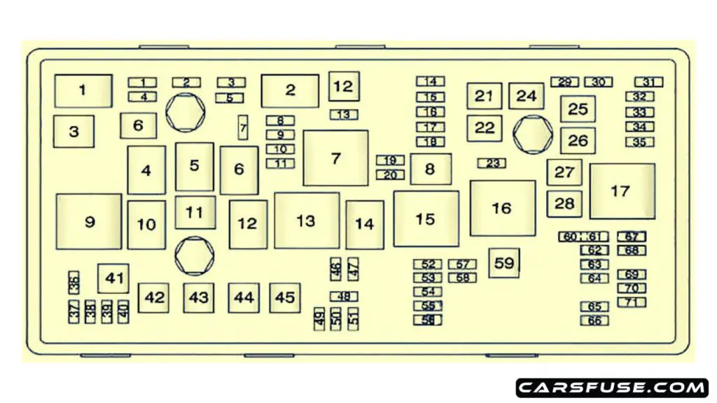
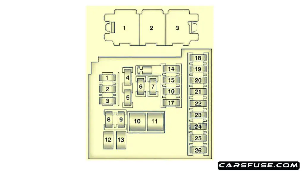
Cigar lighter / power outlet fuses in the Chevrolet Orlando are the fuses №6 (Cigar Lighter), №7 (Power Outlet) and No.26 (Auxiliary Power Outlet) in the Instrument panel fuse box.
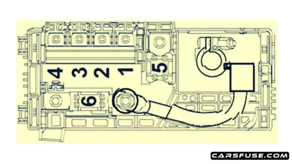
Engine Compartment

2011-2018-Chevrolet-Orlando-J309-engine-cmpartment-fuse-box-diagram-carsfuse.com
Fuse NumberDescriptionFuse Amp
1Transmission Control Module15
2Engine Control Module15
3Not Used
5Transmission Control Module, Engine Control Module, Mass Air Flow/Intake Air Temperature Sensor, Output Speed Sensor15
6Windshield Wiper Relays30
7Not Used
8Fuel injectors15
9Ignition Coil, Fuel Injectors15
10Engine Control Module, Output Speed Sensor15
11Heated Oxygen Sensors10
12Starter Motor30
13Evaporative Emission (EVAP) Canister Vent Solenoid Valve7.5
14Not Used
15Rear Wiper
16Air Quality Sensor7.5
17Inflatable Restraint Sensing and Diagnostic Module5
18Fuel Pump Control Module10
19Not Used
20Fuel Pump Relay20
21Windows Motors, Front Door30
22Not Used
23Not Used
24Windows Motors, Front Door30
25Electronic Vacuum Pump
26Electronic Brake Control Module (EBCM)40
27Remote Control Door Lock Receiver30
28Rear Demister Grid40
29Not Used
30Electronic Brake Control Module (EBCM)15
31Body Control Module20
32Body Control Module20
33Heated Seat Control Module30
34Sunroof Control Module25
35Audio Amplifier30
36Not Used
37Headlamp – Right Main beam10
38Headlamp – Left Main beam10
39Not Used
40Not Used
41Not Used
42Cooling Fan Relays, Cooling Fan Motor20/30
43Not Used
44Not Used
45Cooling Fan High Speed Relay, Cooling Fan Motor30/40
46Cooling Fan Relays10
47Heated Oxygen Sensors, Throttle Body10
48Fog Lights, Front15
49Not Used
50Not Used
51Horn15
52Instrument Cluster5
53Inside Rearview Mirror10
54Headlamp Switch, Electrical Auxiliary Heater, HVAC Control Module5
55Window Switches, Front, Mirror Switch7.5
56Windscreen Washer Pump15
57Steering Column Lock Control Module15
58Not Used
59Fuel Heater30
60Outside Rearview Mirrors7.5
61Mirror Defogger
62A/C Compressor Clutch Relay, A/C Compressor Clutch10
63Rear Window Sensor
64Inflatable Restraint Sensing and Diagnostic Module5
65Rear Fog Lamp
66Rear Washer
67Fuel Pump Control Module20
68Not Used
69Body Control Module5
70Rain Sensor5
71Not Used
Relays:
1A/C Compressor Clutch
2Starter
3Cooling Fan
4Windshield Wiper Speed Control
5Windshield Wiper
6Not Used
7Powertrain
8Fuel Pump
9Cooling Fan Medium Speed 1
10Cooling Fan Medium Speed 2
11Not Used
12Cooling Fan Speed Control (Or in Relay Block – Under-bonnet)
13Cooling Fan High Speed Relay
14Not Used
15Ignition Main Relay
16Fuel Heater Relay
17Rear Window Defogger
Non-serviceable relays (Printed Circuit Board (PCB):
Horn Relay
Windscreen Washer Pump Relay
Front Fog Lamp Relay
Headlamp High Beam Relay

Engine Pre-Fuse Box

2011-2018-Chevrolet-Orlando-J309-engine-pre-fuse-box-diagram-01-carsfuse.com
Fuse NumberDescriptionFuse Amp
1Fuse Block – Instrument Panel100
2Fuse Block – Instrument Panel100
3Electrical Power Steering (EPS) (NJ1)80
4Not Used
5Fuse Block – Battery Auxiliary250
6Starter Motor250/500
2011-2018-Chevrolet-Orlando-J309-enine-pre-fuse-box-diagram-02-carsfuse.com
Fuse NumberDescriptionFuse Amp
5Glow Plug Control Module80
6Electrical Auxiliary Heater100
7Not Used
8Not Used

Relay Box

2011-2018-Chevrolet-Orlando-J309-relay-fuse-box-diagram-carsfuse.com
Relay NumberRelays
1Cooling Fan Left Medium Speed Relay
2Cooling Fan Speed Control 2 Relay
3Cooling Fan Right Medium Speed Relay

Instrument Panel

2011-2018-Chevrolet-Orlando-J309-instrument-panel-fuse-box-diagram-carsfuse.com
Fuse NumberDescriptionFuse Amp
1Mobile Telephone Control Module10
2DC/DC Converter
3Body Control Module25
4Radio20
5Parking Assist Control Module, Power Sounder, Multifunction Switch – Centre Console, Display7.5
6Cigar Lighter20
7Power Outlet20
8Body Control Module30
9Body Control Module30
10Body Control Module30
11Blower Motor Control Module40
12Not Used
13Heated Seat Control Module25
14Data Link Connector, Oil Feeding Connector7.5
15Inflatable Restraint Sensing and Diagnostic Module10
16Rear Compartment Lid Release Relay10
17HVAC Control Module / HVAC Control Assembly15
18Trailer
19Battery Sensor
20Not Used
21Instrument Cluster15
22Ignition Switch2
23Body Control Module20
24Body Control Module20
25Not Used
26Auxiliary Power Outlet20
Non-serviceable relays (Printed Circuit Board (PCB)):
1Tailgate Release Relay
2Logistic Mode Relay 1
3Auxiliary Power Relay

Next Post : 1996-2003 Mercedes-Benz Vito (W638) fuse box diagram

Tom Smith is a passionate car mechanic and automotive enthusiast, specializing in the intricate world of car fuse boxes. With years of hands-on experience under the hood, he has earned a reputation as a reliable expert in his field. As the founder and content creator of the popular blog website 'carsfuse.com,' Tom has dedicated himself to sharing his extensive knowledge of car fuse boxes and electrical systems with the world.

Leave a comment