This guide provides the fuse box diagrams for the 2010-2016 Ford F-250, F-350, F-450, and F-550. Whether you need to check, replace, or troubleshoot fuses, these diagrams make it easy to locate and identify each fuse and relay.
Below, you will find detailed fuse box diagrams and layouts for all these Ford Super Duty models.
Table of Contents
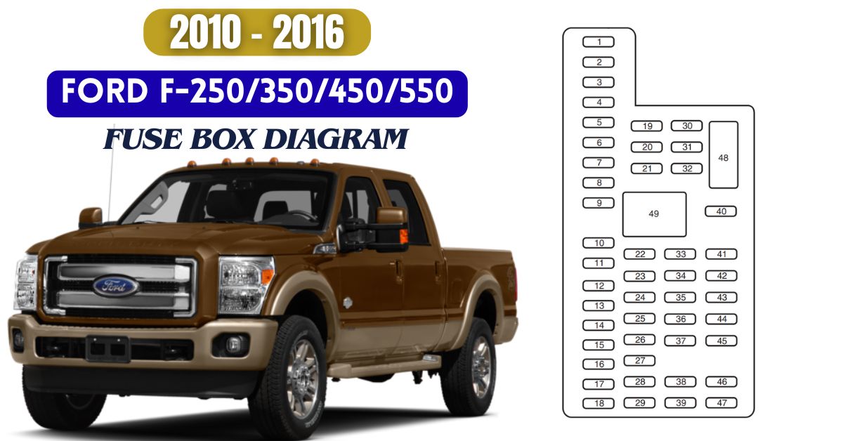
2010 Ford F-250/F-350/F-450/F-550 Fuse Box Diagram
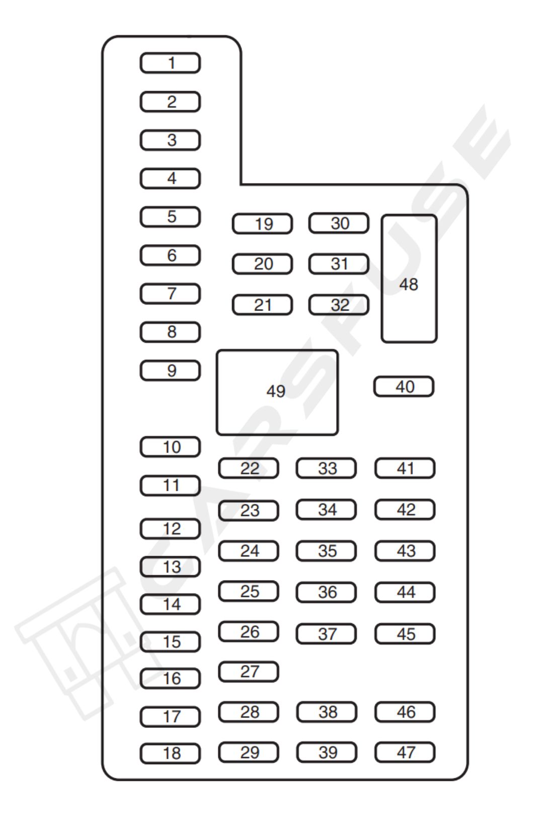
The 2010 Ford F-250/F-350/F-450/F-550 holds two fuse box layout: Power Distribution Box and Passenger Compartment Fuse Panel.
Power Distribution Box
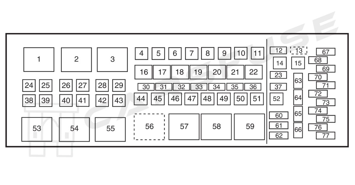
| Fuse/Relay Location | Fuse AmpRating | Protected Circuits |
| 1 | Relay | Blower motor/Variable blower control (Dual zone climate control) |
| 2 | Relay | Electronic shift-on-the-fly (ESOF)Lo-Hi |
| 3 | Relay | Heater mirror |
| 4 | — | Not used |
| 5 | 30A* | Trailer brake controller (TBC) |
| 6 | 40A* | Anti-lock brake system (ABS) module(Pump) |
| 7 | 30A* | Upfitter auxiliary switch #1 |
| 8 | 30A* | Upfitter auxiliary switch #2 |
| 9 | 40A* | ABS module (Coil) |
| 10 | 20A* | Instrument panel power point/cigar lighter |
| 11 | 20A* | Instrument panel power point |
| 12 | 15A** | Brake on/off (BOO) relay feed |
| 13 | 5A** | Brake switch, Brake switch relay coil,SJB module, 4×4 module |
| 14 | — | Not used |
| 15 | — | Not used |
| 16 | Relay | A/C clutch |
| 17 | Relay | Wipers |
| 18 | Relay | Fuel pump driver module (FPDM), Fuel injectors (Gasoline engines), Diesel fuel control module (DFCM)(Diesel engine) |
| 19 | Relay | Back-up lamps, Reverse sensing system (RSS), Engine compartment fuse 63 |
| 20 | Relay | Trailer stop/turn (Left) |
| 21 | Relay | Trailer stop/turn (Right) |
| 22 | Relay | Stop lamps, Center high-mounted stop lamp (CHMSL), TBC, Customer access |
| 23 | 15A** | Heater mirror, Heated spotted mirror |
| 24 | 40A* | Blower motor relay |
| 25 | — | Not used |
| 26 | 30A* | ESOF relay lo-hi |
| 27 | 50A* | Glow plug control module (GPCM) #1(Diesel engine only) |
| 28 | 20A* | Heated mirror relay |
| 29 | 30A* | Passenger power seat |
| 30 | 10A** | A/C clutch relay |
| 31 | 15A** | Power fold mirror relay |
| 32 | 20A** | Fuel pump relay |
| 33 | 20A** | Back-up lamp relay |
| 34 | 25A** | Trailer stop/turn relay |
| 35 | 5A** | ESOF relay coils |
| 36 | 10A** | Gasoline engines: Powertrain control module (PCM) keep alive power, Canister ventDiesel engine: Engine control module (ECM) keep alive power |
| 37 | 10A** | Transmission control module (TCM)(Diesel engine only) |
| 38 | — | Not used |
| 39 | 50A* | ECM power (Diesel engine) |
| 40 | 30A* | Starter relay |
| 41 | 20A* | Power point (Center console – front) |
| 42 | 30A* | Trailer park lamp relay |
| 43 | 20A* | Power point (Center console – rear) |
| 44 | 30A* | Trailer battery charge relay |
| 45 | 30A* | Driver power seat or memory module,Air ride seats |
| 46 | 40A* | Run/Start relay |
| 47 | 50A* | GPCM #2 (Diesel engine only) |
| 48 | 30A* | ESOF relay hi-lo |
| 49 | 30A* | Wiper motor |
| 50 | 30A* | PCM relay coil, PCM relay (Gasoline engines only) |
| 51 | — | Not used |
| 52 | — | Not used |
| 53 | Relay | PCM power bus (Fuses 68, 70, 72, 74,76) (Diesel engine only) |
| 54 | Relay | Starter solenoid |
| 55 | Relay | Trailer tow park lamps |
| 56 | Relay | Trailer tow battery charge |
| 57 | Relay | Power Distribution Box (PDB) bus(fuses 67, 69, 71, 73, 75, 77)SJB Run /Start bus (Fuses 29–37, 46) |
| 58 | Relay | ESOF hi-lo |
| 59 | Relay | PCM power bus (Fuses 68, 70, 72, 74,76) (Gasoline engines only) |
| 60 | Diode | One-touch start (OTIS) |
| 61 | Diode | A/C clutch |
| 62 | Diode | Fuel pump |
| 63 | 15A** | Trailer tow back-up lamps |
| 64 | 5A** | Mirror marker lamps |
| 65 | — | Not used |
| 66 | — | Not used |
| 67 | — | Not used |
| 68 | — | Not used |
| 69 | — | Not used |
| 70 | 10A** | Gasoline engines: A/C clutch relay coil, Refrigerant containment switch,Heated PCVDiesel engine: A/C clutch relay coil, Clutch switch, Fuel pump cooler, A/C cycle pressure switch |
| 71 | 5A** | Fuel pump relay diode, PCM/ECMRun/Start power |
| 72 | 15A** | Gasoline engines: Ignition coilsDiesel engine: Engine TCM |
| 73 | 2A** | Reverse Camera System (RCS) |
| 74 | 20A** | Gasoline engines: Vehicle power (VPWR): Heated exhaust gas oxygen sensor, CMS, Mass air flow sensor, Electronic vapor management valve,CMCV, Variable cam timing, IMTV Diesel engine: VPWR: Engine loads |
| 75 | 5A** | Back-up relay coil power |
| 76 | 20A** | Gasoline engines: VPWR: PCMDiesel engine: VPWR: ECM |
| 77 | 10A** | ABS module logic |
| * Cartridge fuses ** Mini fuses | ||
Passenger Compartment Fuse Panel
| Fuse/RelayLocation | Fuse AmpRating | Protected Circuits |
| 1 | 30A | Not used (spare) |
| 2 | 15A | Not used (spare) |
| 3 | 15A | Family entertainment system (FES) |
| 4 | 30A | Not used (spare) |
| 5 | 10A | Keypad illumination, Brake-shift interlock (BSI), SPBJB |
| 6 | 20A | Turn signals |
| 7 | 10A | Left headlamp (Low beam) |
| 8 | 10A | Right headlamp (Low beam) |
| 9 | 15A | Interior lighting, Lighted running boards |
| 10 | 15A | Cargo lamp, Puddle lamp, Switch backlight |
| 11 | 10A | Not used (spare) |
| 12 | 7.5A | Power mirror switch, Driver power seat (Memory) |
| 13 | 5A | Not used (spare) |
| 14 | 10A | Upfitter relay #3 feed |
| 15 | 10A | Climate control head |
| 16 | 15A | Upfitter relay #4 Feed |
| 17 | 20A | All lock motor feeds |
| 18 | 20A | Heated seat relay feed |
| 19 | 25A | Not used (spare) |
| 20 | 15A | Adjustable pedals, Datalink |
| 21 | 15A | Fog lamp relay feed, Cornering lamps |
| 22 | 15A | Park lamp relay feed |
| 23 | 15A | High beam headlight relay feed |
| 24 | 20A | Horn relay feed |
| 25 | 10A | Power telescoping mirror switch, Demand lamps – underhood and illuminated visor (battery saver) |
| 26 | 10A | Cluster |
| 27 | 20A | Ignition switch feed, Passenger compartment fuses 28, 42, 43, 44, and 45, Engine compartment starter relay coil #57 (Diesel engine), Accessory shutoff control module (if equipped) (Diesel engine), Engine compartment starter relay diode (gasoline engines) |
| 28 | 5A | Radio |
| 29 | 5A | Not used (spare) |
| 30 | 5A | Not used (spare) |
| 31 | 10A | Not used (spare) |
| 32 | 10A | Restraints control module (RCM), Passenger airbag deactivation indicator |
| 33 | 10A | Trailer tow brake controller, Trailer tow battery charge relay coil |
| 34 | 5A | Not used (spare) |
| 35 | 10A | Reverse sensing system (RSS), 4×4 module, 4×4 solenoid, Traction control switch, Tow/Haul switch (Diesel engine) |
| 36 | 5A | Passive anti-theft system (PATS) transceiver, Cluster control |
| 37 | 10A | Climate control, PTC control |
| 38 | 20A | Subwoofer |
| 39 | 20A | Radio, Navigation radio and amplifier |
| 40 | 20A | 4×4 module, Satellite radio module,SYNC, GPS |
| 41 | 15A | Radio, Auto dimming rear view mirror,Lock switch illumination |
| 42 | 10A | Heated seat relay coil, Upfitter switch relay coils, Heated mirror relay coil |
| 43 | 10A | Fuel tank selector switch, 4×4 module |
| 44 | 10A | Run customer access feed (PTO) |
| 45 | 5A | Front wiper logic, Blower motor relay coil |
| 46 | 7.5A | Not used (spare) |
| 47 | 30A CircuitBreaker | Power windows, Moon roof, Power rear sliding window |
| 48 | Relay | Delayed accessory |
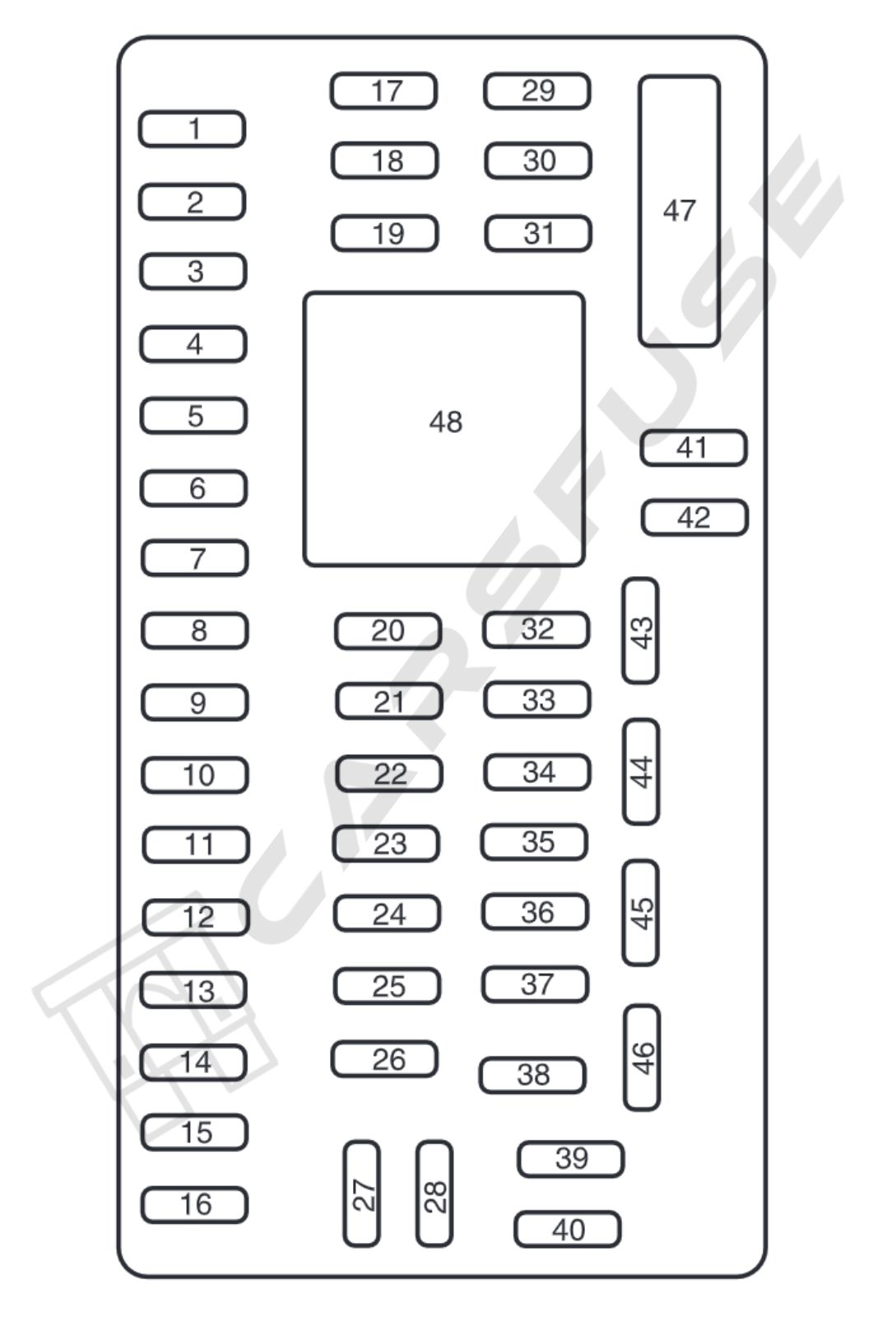
2011-2016 Ford F-250/F-350/F-450/F-550 Fuse Box Diagram
The Ford F-250/F-350/F-450/F-550 from model year 2011 through 2016 holds two fuse box layout: Power Distribution Box and Passenger Compartment Fuse Panel.
Power Distribution Box
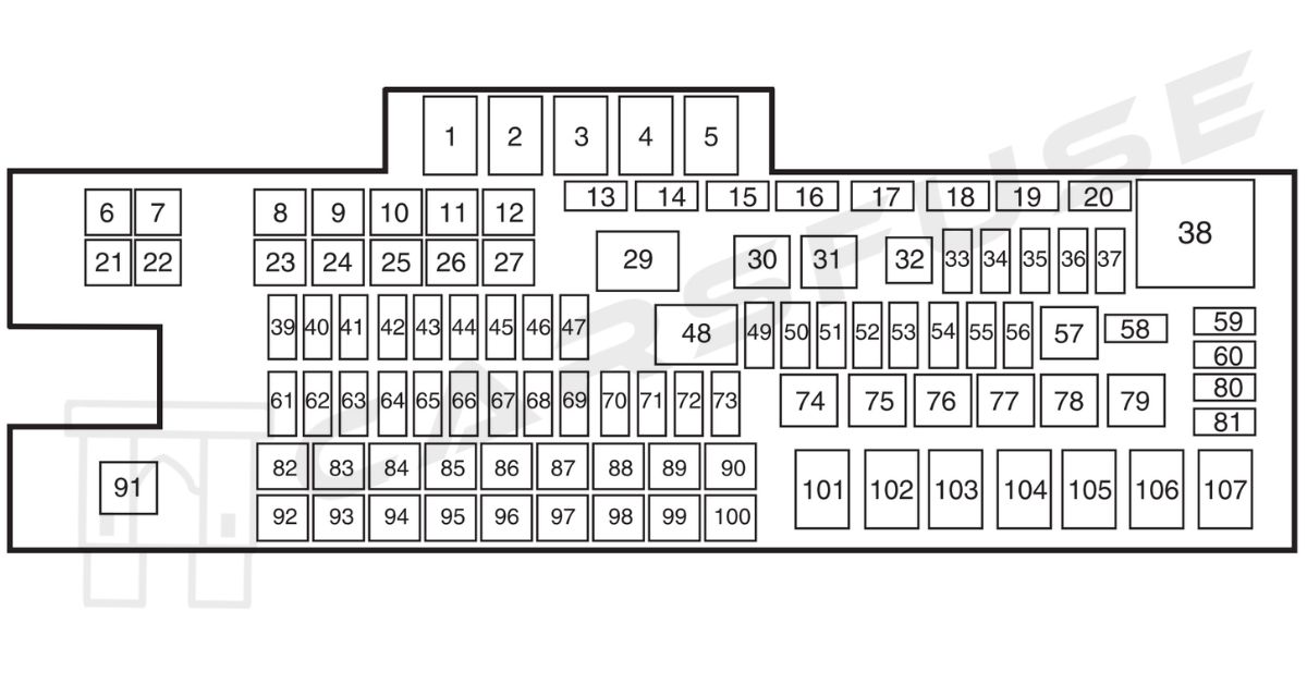
| Fuse/RelayLocation | Fuse AmpRating | Protected Circuits |
| 1 | Relay | Blower motor |
| 2 | — | Not used |
| 3 | Relay | Urea heaters (diesel engine) |
| 4 | — | Not used |
| 5 | Relay | Rear window defroster |
| 6 | — | Not used |
| 7 | 50A* | Rear window defroster |
| 8 | 30A* | Passenger seat |
| 9 | 30A* | Driver seat |
| 10 | — | Not used |
| 11 | — | Not used |
| 12 | — | Not used 2013, 2014, 2015, 2016 Model Year – Smart Window Motor (30A*) |
| 13 | — | Not used |
| 14 | — | Not used |
| 15 | Diode | Fuel pump (diesel engine) |
| 16 | — | Not used |
| 17 | 15A** | Heated mirror |
| 18 | — | Not used |
| 19 | — | Not used |
| 20 | — | Not used |
| 21 | — | Not used |
| 22 | 30A* | Trailer tow electric brake |
| 23 | 40A* | Blower motor |
| 24 | — | Not used |
| 25 | 30A* | Wipers |
| 26 | 30A* | Trailer tow park lamps |
| 27 | 25A* | Urea heaters (diesel engine) |
| 28 | — | Buss bar |
| 29 | Relay | Trailer tow park lamps |
| 30 | Relay | A/C clutch |
| 31 | Relay | Wipers |
| 32 | — | Not used |
| 33 | 15A** | Vehicle power (VPWR) 1 |
| 34 | 15A** | VPWR 2 (diesel engine) |
| 20A** | VPWR 2 (gas engine) | |
| 35 | 10A** | VPWR 3 |
| 36 | 15A** | VPWR 4 (diesel engine) |
| 20A** | VPWR 4 (gas engine) | |
| 37 | 10A** | VPWR 5 (diesel engine) |
| 38 | Relay | Powertrain control module(PCM) (diesel engine),Electronic control module (ECM)(gas engine) |
| 39 | 10A** | 4×4 hub lock |
| 40 | 15A** | 4×4 electronic lock |
| 41 | — | Not used |
| 42 | — | Not used |
| 43 | — | Not used |
| 44 | — | Not used |
| 45 | 10A** | Run/start relay coil |
| 46 | 10A** | Transmission control module (TCM) keep-alive power (diesel engine) |
| 47 | 10A** | A/C clutch feed |
| 48 | Relay | Run/start |
| 49 | 10A** | Rearview camera system |
| 50 | 10A** | Blower motor relay coil |
| 51 | — | Not used |
| 52 | 10A** | PCM/ECM/TCM run/start |
| 53 | 10A** | 4×4 module |
| 54 | 10A** | Anti-lock brake system (ABS) run/start |
| 55 | 10A** | Rear window defroster coil, Battery charge coil |
| 56 | 20A** | Passenger compartment fuse panel run/start feed |
| 57 | Relay | Fuel pump |
| 58 | — | Not used |
| 59 | — | Not used |
| 60 | — | Not used |
| 61 | — | Not used |
| 62 | — | Not used |
| 63 | — | Not used |
| 64 | — | Not used |
| 65 | — | Not used |
| 66 | 20A** | Fuel pump |
| 67 | — | Not used |
| 68 | 10A** | Fuel pump relay coil |
| 69 | — | Not used |
| 70 | 10A** | Trailer tow backup lamp |
| 71 | 10A** | Cannister vent (gas engine) |
| 72 | 10A** | PCM/ECM relay coil feed keep-alive power |
| 73 | — | Not used |
| 74 | Relay | Trailer tow left-hand stop/turn |
| 75 | Relay | Trailer tow right-hand stop/turn |
| 76 | Relay | Backup lamp |
| 77 | — | Not used |
| 78 | — | Not used |
| 79 | — | Not used |
| 80 | — | Not used |
| 81 | — | Not used |
| 82 | 20A* | Auxiliary power point #2 |
| 83 | 20A* | Auxiliary power point #1 |
| 84 | 30A* | 4×4 shift motor |
| 85 | 30A* | Heated/cooled seats |
| 86 | 25A* | ABS coil feed |
| 87 | 20A* | Auxiliary power point #5 |
| 88 | — | Not used |
| 89 | 40A* | Starter motor |
| 90 | 25A* | Trailer tow battery charge |
| 91 | — | Not used |
| 92 | 20A* | Auxiliary power point #4 |
| 93 | 20A* | Auxiliary power point #3 |
| 94 | 25A* | Upfitter #1 |
| 95 | 25A* | Upfitter #2 |
| 96 | 50A* | ABS pump |
| 97 | 40A* | Invertor |
| 98 | — | Not used |
| 99 | — | Not used |
| 100 | 25A* | Trailer tow turn signals |
| 101 | Relay | Starter |
| 102 | Relay | Trailer tow battery charge |
| 103 | — | Not used |
| 104 | — | Not used |
| 105 | — | Not used |
| 106 | — | Not used |
| 107 | — | Not used |
| * Cartridge fuses ** Mini fuses | ||
Passenger Compartment Fuse Panel
| Fuse/RelayLocation | Fuse AmpRating | Protected Circuits |
| 1 | 30A | Not used (spare) |
| 2 | 15A | Upfitter relay #4 |
| 3 | 30A | Not used (spare) |
| 4 | 10A | Telescoping mirror switch, Interior lights, Hood lamp |
| 5 | 20A | Moon roof |
| 6 | 5A | Driver seat module |
| 7 | 7.5A | Driver seat switch, Driver lumbar motor |
| 8 | 10A | Power mirror switch |
| 9 | 10A | Upfitter relay #3 |
| 10 | 10A | Run/accessory relay, Customer access feed |
| 11 | 10A | Instrument cluster |
| 12 | 15A | Interior lighting, Lighted running board lamps |
| 13 | 15A | Right turn signals and brake lamps, Right trailer tow (TT) stop turn relay |
| 14 | 15A | Left turn signals and brake lamps,Left TT stop turn relay |
| 15 | 15A | High-mounted stop lamps, Backup lamps, TT backup relay |
| 16 | 10A | Right low beam headlamp |
| 17 | 10A | Left low beam headlamp |
| 18 | 10A | Keypad illumination, Passive anti-theft indicator (PATS), Powertrain control module(PCM), Brake shift interlock |
| 19 | 20A | Subwoofer Amplifier (For 2013 Model Year Only) |
| 20 | 20A | Power door locks |
| 21 | 10A | Brake on/off switch |
| 22 | 20A | Horn |
| 23 | 15A | Not used (spare) |
| 24 | 15A | Steering wheel control module, Diagnostic connector, Satellite radio module, Power fold mirror relay, Remote keyless entry |
| 25 | 15A | Not used (spare) |
| 26 | 5A | Steering wheel control module |
| 27 | 20A | Amplifier |
| 28 | 15A | Ignition switch |
| 29 | 20A | SYNC, GPS module, Radio faceplate |
| 30 | 15A | Parking lamp relay, TT parking lamp relay |
| 31 | 5A | Trailer brake controller (brake signal), Customer access |
| 32 | 15A | Moonroof motor, Telescoping mirror switch, Auto dimming mirrors, Power inverter, Driver and passenger door lock switch illumination, Rear heated seat switch illumination |
| 33 | 10A | Restraint control module |
| 34 | 10A | Not used (spare) |
| 35 | 5A | Select shift switch, Reverse park aid module, Trailer brake control module |
| 36 | 10A | Fuel tank select switch |
| 37 | 10A | PTC heater |
| 38 | 10A | Radio faceplate |
| 39 | 15A | High beam headlamps |
| 40 | 10A | Parking lamps (in mirrors), Roof marker lamps |
| 41 | 7.5A | Passenger airbag deactivation indicator |
| 42 | 5A | Not used (spare) |
| 43 | 10A | Wiper relay |
| 44 | 10A | Upfitter switches |
| 45 | 5A | Not used (spare) |
| 46 | 10A | Climate control |
| 47 | 15A | Fog lamps, Fog lamp indicator (in switch) |
| 48 | 30A Circuit Breaker | Power windows switch, Power rear sliding window switch |
| 49 | Relay | Delayed accessory |
Tip: Some high-amperage fuses may look slightly different depending on the model year and trim. Always verify the fuse type before replacing.
Fuse Replacement Tips / Safety Precautions
- Always disconnect the negative battery terminal before removing fuses.
- Never replace a blown fuse with a higher amp rating — this can damage wiring or cause a fire.
- Use a fuse puller or needle-nose pliers for safety.
- Label replaced fuses for future reference.
Frequently Asked Questions (FAQs)
Why does my cigarette lighter or power socket fuse keep blowing?
This usually means the circuit is carrying more power than it should, has a short, or the wrong fuse is installed.
Overload: Plugging in high-demand gadgets like tire inflators or power inverters.
Short circuit: Damaged or exposed wires making contact with metal parts.
Bad adapters: Cheap or faulty chargers pulling too much current.
Incorrect fuse: A fuse rated lower than Ford’s specification.
Why does the radio fuse keep blowing?
A blown radio fuse often points to a wiring fault or too much power draw.
Short circuit: Exposed or damaged wires contacting metal.
Added accessories: Extra amps or aftermarket add-ons overloading the system.
Wrong fuse: Fuse with a lower rating than Ford’s recommendation.
Faulty radio: Internal malfunction causing excess current flow.
Power surges: Voltage spikes from alternator or battery issues.
Why does my light fuse keep blowing?
Fog light fuse problems often come down to wiring, bulbs, or aftermarket changes.
Short circuit: Wires rubbing against metal surfaces.
Defective bulb: Faulty or shorted bulb causing overcurrent.
Bad switch: Worn or damaged fog light switch sending irregular current.
Lighting upgrades: Added LED or aftermarket fog lights exceeding circuit limits.
Why does the tail light fuse keep blowing?
Tail light fuse issues typically involve the wiring, bulbs, or switch.
Short circuit: Frayed or melted wires grounding out.
Wrong or bad bulb: Incorrect or damaged bulb causing excess current draw.
Faulty switch: Malfunctioning light switch sending power surges.
Incorrect fuse: Using a fuse with a lower rating than specified.
Why does the horn relay fail in my F-250?
Horn relay failure is usually caused by electrical faults or natural wear.
Short circuit: Wiring faults causing too much current to pass through.
Component wear: Relay contacts or coil breaking down with age.
Voltage surges: Sudden spikes damaging the relay or nearby parts.