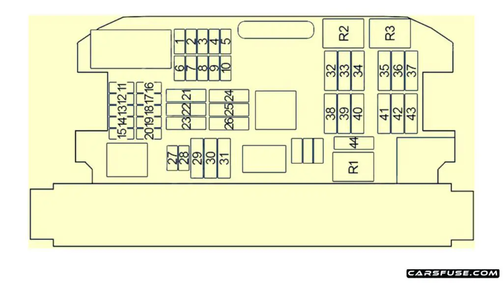
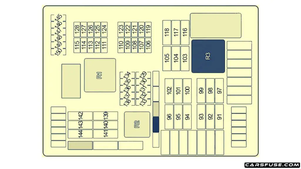
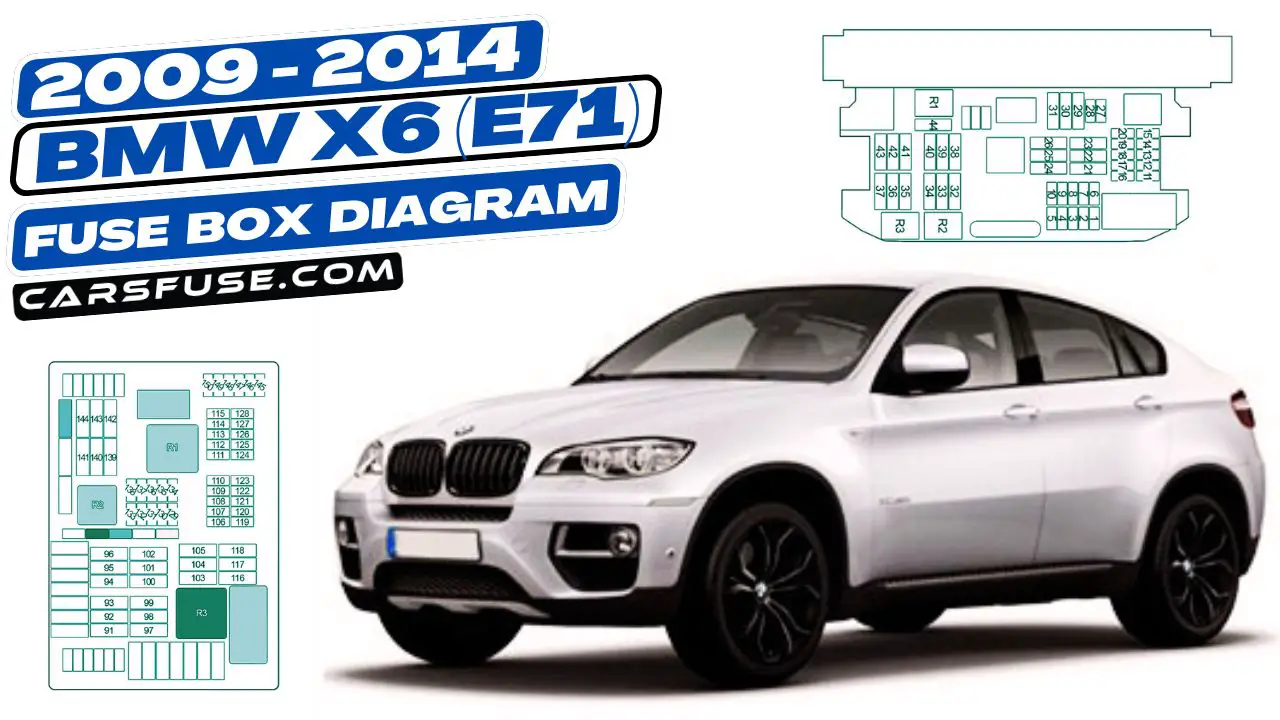
The first-generation BMW X6 (E71/E72) was manufactured from 2008 to 2014. In this guide, you’ll find fuse box diagrams for BMW X6 models from 2008 to 2014. You’ll also discover the locations of the fuse panels within the vehicle and detailed information on the assignment and layout of each fuse and relay.
Table of Contents
Fuse Box Location
- The instrument panel can be found beneath the glove compartment.
- The luggage compartment is situated on the right side, concealed behind a panel.
Instrument panel

| Number | Fuse Amps | Protected Component |
|---|---|---|
| 1 | 20A | Steering Column Adjustment Motor, Heating/Air Conditioning System |
| 2 | 10A | Glove Compartment Unlock Drive Unit, Glove Compartment Light (2009-2014) |
| 3 | 7.5A | Siren and Tilt Alarm Sensor |
| 4 | 10A | except N55: Digital Motor Electronics (DME) Module N55: Integrated Supply Module ActiveHybrid: Digital Motor Electronics (DME) Module |
| 5 | 10A | Roof Function Control Centre |
| 6 | 10A | iDrive Controller, DVD-Changer, CD Changer, Video Selector Switch |
| 7 | 5A | Active Cruise Control, Longitudinal Dynamics Management, Tyre Pressure Control (RDC) |
| 8 | 7.5A | Vertical Dynamics Management (Front Left/Right Damper Satellite) |
| 9 | 15A | Horn Relay (Left/Right Horn) |
| 10 | 5A | Parking Brake, Car Access System |
| 11 | 20A | Independent Auxiliary Heater |
| 12 | 10A | Steering Column Switch Center |
| 13 | 15A | Transmission Control |
| 14 | 10A | Dynamic Drive |
| 15 | 10A | Gear Selector Switch |
| 16 | 10A | Driver’s Door Switch Block, Driver’s Side Outside Mirror, Passenger’s Side Outside Mirror |
| 17 | 5A | Central Information Display, Heating/Air Conditioning System (without Electrical Steering Column Adjustment), Active Video Switch (Japan) |
| 18 | 7.5A | Head-Up Display, E-Box Fan, Fuel Tank Vent Valve (2008-2011), Tank Vent Shutoff Valve (2011-2014) |
| 19 | 5A | Dynamic Stability Control (DSC), Roof Function Control Centre (without Sunroof) |
| 20 | 10A | Integrated Chassis Management (ICM), Servotronic (without ICM) |
| 21 | 30A | Rear Window Defogger |
| 22 | 5A | Left Headlight |
| 23 | 40A | Footwell Module |
| 24 | 40A | Active Steering |
| 25 | 5A | Right Headlight |
| 26 | 25A30A | Headlight Washer Pump |
| 27 | 15A/20A | Central Locking System |
| 28 | 15A | Central Locking System |
| 29 | 40A | Rear Driver’s Side Power Window Motor |
| 30 | 30A | Central Locking System |
| 31 | 40A | Rear Passenger’s Side Power Window Motor |
| 32 | 40A | Air Suspension Compressor |
| 33 | 30A | Footwell Module |
| 34 | 30A | Footwell Module |
| 35 | 30A | N63, S63, ActiveHybrid: Oxygen Sensors |
| 36 | 30A | N63, ActiveHybrid: VANOS Solenoid Valve №2 – intake, VANOS Solenoid Valve №2 – exhaust, Crankshaft Sensor, Blow-Off Valve, клапан рециркуляции №2, Air Mass Flow Sensor (№1, №2) |
| 37 | – | – |
| 38 | 30A | N57: SCR Load Relay |
| 39 | 40A | Car Access System |
| 40 | 30A | Dynamic Stability Control (DSC) |
| 41 | 7.5A | N63, S63, ActiveHybrid: Coolant Pump for Charge Air Cooler №2, Radiator Shutter Drive Unit N54: Hot-Film Air Mass Meter, Radiator Shutter Drive Unit |
| 42 | 30A | N63, S63, ActiveHybrid: Digital Motor Electronics (DME) Module, Coolant Pump for Intercooler, Volume Control Valve, Wastegate Valve Pressure Converter (№1, №2) N54: Digital Motor Electronics (DME) Module, Fuel Tank Vent Valve, Crankshaft Sensor, Volume Control Valve, Oxygen Sensors (before Catalytic Converter) |
| 43 | 30A | N63, S63, ActiveHybrid: Intake Camshaft Sensor (№1, №2), Exhaust Camshaft Sensor (№1, №2), Oil Condition Sensor, Fuel Tank Vent Valve, Characteristic Map Thermostat, Coolant Pump for Intercooler N54: Oxygen Sensors (after Catalytic Converter), Oil Condition Sensor |
| 44 | 30A | Front Wiper Motor |
| 45 | 60A | Electric Fan Cut-Out Relay (Electric Fan) |
| 46 | 40A | Dynamic Stability Control (DSC) |
| 47 | 40A | N57, M57US: Fuel Heater |
| 48 | 40A | Blower Output Stage |
| 49 | – | – |
Luggage compartment

| Number | Fuse Amps | Protected Component |
|---|---|---|
| 91 | 30A | Rear Right Electric Auxiliary Heater |
| 92 | 25A/30A | Transfer Box Control Unit |
| 93 | 30A | Rear Axle Transverse Torque Distribution (QMVH) |
| 94 | 30A | Parking Brake Control Unit |
| 95 | 30A | Rear Left Electric Auxiliary Heater |
| 96 | 40A | Footwell Module |
| 97 | 20A | 2008: Fuel Pump Relay (without Electronically Controlled Fuel Pump), Fuel Pump Control (EKPS) (with Electronically Controlled Fuel Pump) |
| 98 | 15A | Rear Compartment Blower Motor |
| 99 | 40A | 2008: Boot Lid Lift |
| 100 | 20A | Rear Left Seat Heating Module, Terminal 15 Power-Saving Relay (without Rear Compartment Air Conditioning) |
| 101 | 30A | Driver’s Seat Module, Driver’s Seat Adjustment Switch, Driver’s Lumbar Support Switch |
| 102 | 30A | Passenger’s Seat Module, Passenger’s Seat Adjustment Switch, Passenger’s Lumbar Support Switch |
| 103 | 30A/40A | Audio Amplifier |
| 104 | 25A | Electrically Operated Towing Hitch |
| 105 | 20A | 2009-2014: Fuel Pump Relay (without Electronically Controlled Fuel Pump), Fuel Pump Control (EKPS) (with Electronically Controlled Fuel Pump) |
| 106 | 7.5A | Vertical Dynamics Management (Rear Left/Right Damper Satellite) |
| 107 | 10A | Electronic Ride Height Control, Rear Compartment Display (2008-2012), Tyre Pressure Control – RDC (2012-2014) |
| 108 | 5A | Reversing Camera, Rear Seat Entertainment, Headset Socket, Headset Connection Module |
| 109 | 10A | 2008-2012: Satellite Receiver (2008-2011), Digital Tuner (USA) (2008-2009), Tyre Pressure Control – RDC (2010-2014) |
| 109 | 15A | 2012-2014: Active Sound Design (ASD) |
| 110 | 7.5A/5A | Luggage Compartment Light, Noise Suppressor Filter, Interface Box High (ULF-SBX-H), Telematics (TCU), Interface Box (ULF-SBX), Telephone Eject Box, USB Hub |
| 111 | 20A | Front Cigar Lighter, Rear Centre Console Charging Socket |
| 112 | 5A | Driver’s Seat Heating Module, Passenger’s Seat Heating Module, Terminal 15 Power-Saving Relay, Rear Left Seat Heating Module, Rear Right Seat Heating Module |
| 113 | 20A | Luggage Compartment Charging Socket, Centre Console 12V Socket |
| 114 | 5A | Roof Function Control Centre, Park Distance Control (PDC), All-Round Vision Camera, Camera-Based Driver Support Systems |
| 115 | 20A | Rear Cigar Lighter, Rear Socket Outlet |
| 116 | 20A | Trailer Socket |
| 117 | 20A | Roof Function Control Centre (Sunroof) |
| 118 | – | – |
| 119 | 5A/10A | Video Module |
| 120 | 5A | Vertical Dynamics Management |
| 121 | 5A | Boot Lid Lift |
| 122 | 5A | Diagnostic Module for Fuel Tank Leakage |
| 123 | 5A | Rear Axle Transverse Torque Distribution (QMVH) |
| 124 | 5A | Junction Box Electronics (JBE) |
| 125 | 5A | Transfer Box Control Unit |
| 126 | 5A | Rear Compartment Air Conditioning Control Unit |
| 127 | 5A | Electric Fan Cut-Out Relay |
| 128 | 5A | Exhaust Flap |
| 129 | 5A | Parking Brake Control Unit, Aerial Diversity |
| 130 | 15A | S63, N63, ActiveHybrid: Coolant Pump for Charge Air Cooler № 2, Coolant Pump for Intercooler N57: Coolant Pump for Charge Air Cooler |
| 131 | 5A | 2008-2009: Instrument Cluster, Diagnostic Connector OBD II 2009-2012: Active Sound Design (ASD) |
| 132 | 7.5A | Audio Amplifier Active Sound Design – ASD (2009-2014), Comfort Access Control Unit, Passenger’s Side Outer Door Handle Electronic Module, Rear Left Electronic Outer Door Handle Module, Rear Right Electronic Outer Door Handle Module |
| 133 | 5A | ActiveHybrid: Interface Box |
| 134 | 5A | Steering Column Switch Center, Diagnostic Connector OBD II, Instrument Cluster |
| 135 | 20A | Boot Lid/Tailgate Automatic Soft-Close Drive |
| 136 | 5A | Telematics (TCU), Telephone Eject Box Combox Media |
| 137 | 5A | Navigation System |
| 138 | 10A | Electrically Operated Towing Hitch |
| 139 | 20A | Rear Right Seat Heating Module |
| 140 | 20A | Driver’s Seat Heating Module |
| 141 | 20A | Passenger’s Seat Heating Module |
| 142 | 20A | 2008-2009: CCC/M-ASK or CHAMP 2009-2014: Car Information Computer (CIC) |
| 143 | 20A/25A | Trailer Module |
| 144 | 20A/25A | Trailer Module |
| 145 | 10A | Driver’s Door Automatic Soft-Close Drive |
| 146 | 10A | Passenger’s Door Automatic Soft-Close Drive |
| 147 | 10A | Rear Left Automatic Soft-Close Drive |
| 148 | 10A | Rear Right Automatic Soft-Close Drive |
| 149 | 7.5A | Driver’s Seat Adjustment Switch |
| 150 | 7.5A | Passenger’s Seat Adjustment Switch |
Next Post: 2010-2015 BMW X1 (E84) fuse box diagram
Tom Smith is a passionate car mechanic and automotive enthusiast, specializing in the intricate world of car fuse boxes. With years of hands-on experience under the hood, he has earned a reputation as a reliable expert in his field. As the founder and content creator of the popular blog website 'carsfuse.com,' Tom has dedicated himself to sharing his extensive knowledge of car fuse boxes and electrical systems with the world.

