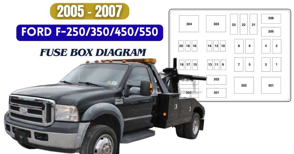
The 2005–2007 Ford F-Series Super Duty trucks—including the F-250, F-350, F-450, and F-550—feature a centralized fuse system that safeguards the vehicle’s electrical components.
Knowing where each fuse is located and what it controls can save time when troubleshooting electrical problems. Below are the fuse box diagrams and descriptions to help you quickly find and replace any blown fuses.
Table of Contents
2005 Ford F-250/F-350/F-450/F-550 Fuse Box Diagram
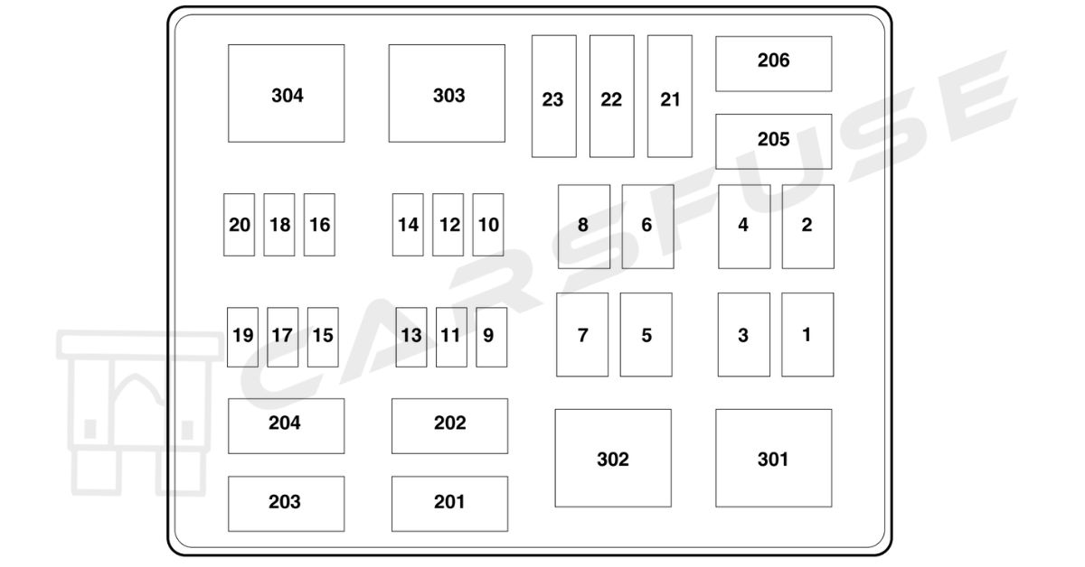
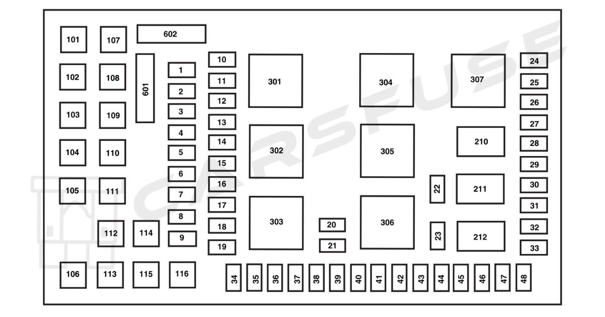
In 2005, the Ford F-Series Super Duty trucks came with two fuse boxes: the Power Distribution Box and the Passenger Compartment Fuse Panel.
Power Distribution Box

| Fuse/Relay Location | Fuse Amp Rating | Description |
| 1 | 30A* | Wipers |
| 2 | 40A* | Blower |
| 3 | 30A* | Electronic Shift on the Fly (ESOF) |
| 4 | — | Not used |
| 5 | 50A* | Injector Driver Module (IDM)(Diesel engine only) |
| 6 | — | Not used |
| 7 | 30A* | Horizontal Fuel Conditioner Module (HFCM) (Diesel engine only) |
| 8 | — | Not used |
| 9 | 20A** | Trailer tow turn signals |
| 10 | 10A** | Powertrain Control Module (PCM) keep alive power, Canister vent solenoid (gasoline engine only) |
| 11 | 10A** | Anti-lock Brake System (ABS) |
| 12 | 2A** | Brake pressure switch |
| 13 | 15A** | Daytime Running Lamps (DRL) |
| 14 | — | Not used |
| 15 | 15A** | IDM logic (Diesel engine only) |
| 16 | — | Not used |
| 17 | 10A** | A/C clutch |
| 18 | 10A** | IDM relay (Diesel engine only) |
| 19 | — | Not used |
| 20 | 10A** | Trailer tow back-up lamps |
| 21 | — | Not used |
| 22 | 60A*** | ABS (Coils) |
| 23 | 60A*** | ABS (Pump) |
| 201 | 1⁄2 ISO relay | Trailer tow right turn signal/stop lamp |
| 202 | 1⁄2 ISO relay | Trailer tow left turn signal/stop lamp |
| 203 | 1⁄2 ISO relay | A/C clutch |
| 204 | — | Not used |
| 205 | 1⁄2 ISO relay | DRL #1 |
| 206 | 1⁄2 ISO relay | DRL #2 |
| 301 | Full ISO relay | DRL #3 |
| 302 | Full ISO relay | HFCM |
| 303 | Full ISO relay | Blower |
| 304 | High-current relay | IDM (Diesel engine only) |
| * Cartdrige Fuse ** Mini Fuses *** Maxi fuse | ||
Passenger Compartment Fuse Panel

| Fuse/RelayLocation | Fuse AmpRating | Description |
| 1 | 15A* | Adjustable pedals |
| 2 | 10A* | Cluster |
| 3 | 10A* | Upfitter #3 |
| 4 | 20A* | Power point (Instrument panel) |
| 5 | 10A* | Upfitter #4 |
| 6 | — | Not used |
| 7 | 30A* | High beam headlamps, Flash-to-pass |
| 8 | 20A* | Back-up lamps |
| 9 | — | Not used |
| 10 | — | Not used |
| 11 | 20A* | Radio (Main) |
| 12 | 20A* | Cigar lighter, OBD II |
| 13 | 5A* | Power mirrors |
| 14 | — | Not used |
| 15 | — | Not used |
| 16 | — | Not used |
| 17 | 15A* | Exterior lamps |
| 18 | 20A* | Flasher, Brake On-Off (BOO) lamps |
| 19 | 10A* | Body Security Module (BSM)(Security) |
| 20 | 15A* | Trailer tow Electric Brake Controller (EBC) |
| 21 | 20A* | Heated seats |
| 22 | 20A* | Engine control |
| 23 | 20A* | Engine control (gasoline engine only)/Climate control (Diesel engine only) |
| 24 | 15A* | Tow haul, Blower relay, Electronic Automatic Temperature Control(EATC) |
| 25 | — | Not used |
| 26 | 10A* | Air bags |
| 27 | 15A* | Ignition switch RUN feed |
| 28 | 10A* | Trailer tow EBC logic |
| 29 | 10A* | Customer access |
| 30 | 15A* | High beam headlamps |
| 31 | 15A* | 4×4 |
| 32 | 5A* | Radio (start) |
| 33 | 15A* | Cluster, 4×4, Wipers |
| 34 | 10A* | BOO switch (Low current) |
| 35 | 10A* | Instrument cluster |
| 36 | — | Not used |
| 37 | 15A* | Horn |
| 38 | 20A* | Trailer tow park lamps |
| 39 | 15A* | Heated mirrors |
| 40 | 20A* | Fuel pump |
| 41 | 10A* | Instrument cluster |
| 42 | 15A* | Delayed accessory |
| 43 | 10A* | Fog lamps |
| 44 | — | Not used |
| 45 | 10A* | Ignition switch RUN/START feed |
| 46 | 10A* | Left-hand low beam headlamp |
| 47 | 10A* | Right-hand low beam headlamp |
| 48 | — | Not used |
| 101 | 30A** | Trailer tow EBC |
| 102 | 30A** | BSM (Door locks) |
| 103 | 30A** | Ignition switch |
| 104 | — | Not used |
| 105 | — | Not used |
| 106 | — | Not used |
| 107 | 20A** | Trailer tow battery charge |
| 108 | 30A** | Upfitter #1 |
| 109 | 30A** | Upfitter #2 |
| 110 | 30A** | Ignition switch |
| 111 | — | Not used |
| 112 | 30A** | Power seat (Driver) |
| 113 | 30A** | Starter |
| 114 | 30A** | Power seat (Passenger) |
| 115 | 20A** | Upfitter control |
| 116 | 30A** | Ignition switch |
| 210 | — | Not used |
| 211 | 1⁄2 ISO relay | Back-up lamps |
| 212 | — | Not used |
| 301 | Full ISO relay | Trailer tow battery charge |
| 302 | Full ISO relay | Powertrain Control Module (PCM) |
| 303 | — | Not used |
| 304 | — | Not used |
| 305 | Full ISO relay | Upfitter control |
| 306 | Full ISO relay | Delayed accessory |
| 307 | Full ISO relay | Starter |
| 601 | 30A circuit breaker | Delayed accessory, Power windows, Moonroof |
| 602 | — | Not used |
| * Mini fuse ** Cartridge fuse | ||
2006-2007 Ford F-250/F-350/F-450/F-550 Fuse Box Diagram
For 2006–2007, the Ford F-250, F-350, F-450, and F-550 also feature two fuse boxes: the Power Distribution Box and the Passenger Compartment Fuse Panel.
Power Distribution Box

| Fuse/RelayLocation | Fuse AmpRating | Description |
| 1 | 30A* | Wipers |
| 2 | 40A* | Blower |
| 3 | 30A* | Electronic Shift on the Fly(ESOF) |
| 4 | — | Not used |
| 5 | 50A* | Injector Driver Module (IDM)(Diesel engine only) |
| 6 | — | Not used |
| 7 | — | Not used |
| 8 | — | Shunt |
| 9 | 20A** | Trailer tow turn signals |
| 10 | 10A** | Powertrain Control Module (PCM) keep alive power, Canister vent solenoid (gasoline engine only) |
| 11 | 10A** | Anti-lock Brake System (ABS) |
| 12 | 2A** | Brake pressure switch |
| 13 | 15A** | Daytime Running Lamps (DRL) |
| 14 | — | Not used |
| 15 | 15A** | IDM logic (Diesel engine only) |
| 16 | — | Not used |
| 17 | 10A** | A/C clutch |
| 18 | 10A** | IDM relay (Diesel engine only) |
| 19 | — | Not used |
| 20 | 10A** | Trailer tow back-up lamps |
| 21 | — | Not used |
| 22 | 60A*** | ABS (Coils) |
| 23 | 60A*** | ABS (Pump) |
| 201 | 1⁄2 ISO relay | Trailer tow right turn signal/stop lamp |
| 202 | 1⁄2 ISO relay | Trailer tow left turn signal/stop lamp |
| 203 | 1⁄2 ISO relay | A/C clutch |
| 204 | — | Not used |
| 205 | 1⁄2 ISO relay | DRL #1 |
| 206 | 1⁄2 ISO relay | DRL #2 |
| 301 | Full ISO relay | DRL #3 |
| 302 | — | Not used |
| 303 | Full ISO relay | Blower |
| 304 | High-current relay | IDM (Diesel engine only) |
| * Cartridge Fuse ** Mini Fuses *** Maxi fuse | ||
Passenger Compartment Fuse Panel

| Fuse/Relay Location | Fuse Amp Rating | Description |
| 1 | 15A* | Adjustable pedals |
| 2 | 10A* | Cluster |
| 3 | 10A* | Upfitter #3 |
| 4 | 20A* | Power point (Instrument panel) |
| 5 | 10A* | Upfitter #4 |
| 6 | — | Not used |
| 7 | 30A* | High beam headlamps, Flash-to-pass |
| 8 | 20A* | Back-up lamps |
| 9 | — | Not used |
| 10 | — | Not used |
| 11 | 20A* | Radio (Main) |
| 12 | 20A* | Cigar lighter, OBD II |
| 13 | 5A* | Power mirrors |
| 14 | — | Not used |
| 15 | — | Not used |
| 16 | — | Not used |
| 17 | 15A* | Exterior lamps |
| 18 | 20A* | Flasher, Brake On-Off (BOO) lamps |
| 19 | 10A* | Body Security Module (BSM)(Security) |
| 20 | 15A* | Trailer tow Electric Brake Controller (EBC) |
| 21 | 20A* | Heated seats |
| 22 | 20A* | Engine control |
| 23 | 20A* | Engine control (gasoline engine only)/Climate control (Diesel engine only) |
| 24 | 15A* | Tow haul, Blower relay, Electronic Automatic Temperature Control(EATC) |
| 25 | — | Not used |
| 26 | 10A* | Airbags |
| 27 | 15A* | Ignition switch RUN feed |
| 28 | 10A* | Trailer tow EBC logic |
| 29 | 10A* | Customer access |
| 30 | 15A* | High beam headlamps |
| 31 | 15A* | Starter relay |
| 32 | 5A* | Radio (start) |
| 33 | 15A* | Cluster, 4×4, Wipers |
| 34 | 10A* | BOO switch (Low current) |
| 35 | 10A* | Instrument cluster |
| 36 | — | Not used |
| 37 | 15A* | Horn |
| 38 | 20A* | Trailer tow park lamps |
| 39 | 15A* | Heated mirrors |
| 40 | 20A* | Fuel pump |
| 41 | 10A* | Instrument cluster |
| 42 | 15A* | Delayed accessory |
| 43 | 10A* | Fog lamps |
| 44 | — | Not used |
| 45 | 10A* | Ignition switch RUN/START feed |
| 46 | 10A* | Left-hand low beam headlamp |
| 47 | 10A* | Right-hand low beam headlamp |
| 48 | — | Not used |
| 101 | 30A** | Trailer tow EBC |
| 102 | 30A** | BSM (Door locks) |
| 103 | 30A** | Ignition switch |
| 104 | — | Not used |
| 105 | — | Not used |
| 106 | — | Not used |
| 107 | 20A** | Trailer tow battery charge |
| 108 | 30A** | Upfitter #1 |
| 109 | 30A** | Upfitter #2 |
| 110 | 30A** | Ignition switch |
| 111 | — | Not used |
| 112 | 30A** | Power seat (Driver) |
| 113 | 30A** | Starter |
| 114 | 30A** | Power seat (Passenger) |
| 115 | 20A** | Upfitter control |
| 116 | 30A** | Ignition switch |
| 210 | — | Not used |
| 211 | 1⁄2 ISO relay | Back-up lamps |
| 212 | — | Not used |
| 301 | Full ISO relay | Trailer tow battery charge |
| 302 | Full ISO relay | Powertrain Control Module (PCM) |
| 303 | — | Not used |
| 304 | — | Not used |
| 305 | Full ISO relay | Upfitter control |
| 306 | Full ISO relay | Delayed accessory |
| 307 | Full ISO relay | Starter |
| 601 | 30A circuit breaker | Delayed accessory, Power windows, Moonroof |
| 602 | — | Not used |
| * Mini fuse ** Cartridge fuse | ||
Tip: Some high-amperage fuses may look slightly different depending on the model year and trim. Always verify the fuse type before replacing.
Fuse Replacement Tips / Safety Precautions
- Always disconnect the negative battery terminal before removing fuses.
- Never replace a blown fuse with a higher amp rating — this can damage wiring or cause a fire.
- Use a fuse puller or needle-nose pliers for safety.
- Label replaced fuses for future reference.
Frequently Asked Questions (FAQs)
Why does the cigarette lighter (power socket) fuse keep blowing?
This usually happens when the circuit is overloaded, there’s a short in the wiring, or the wrong fuse is installed. Using high-power devices, damaged wires, or faulty adapters can trigger the fuse to blow. Installing a fuse with lower amperage than Ford recommends can also cause repeated failures.
Why does the radio fuse keep blowing?
Radio fuse problems are often caused by shorted or damaged wires, additional accessories, a faulty radio, or voltage fluctuations. Using a fuse with the wrong amperage can make it blow more easily.
Why does the fog light fuse keep blowing?
Fog light fuses commonly fail due to damaged wiring, a faulty bulb, a defective switch, or modifications that add extra load to the circuit.
Why does the tail light fuse keep blowing?
Tail light fuse issues are usually linked to shorted or damaged wires, bad or incompatible bulbs, a malfunctioning switch, or a fuse with the wrong amperage.
Why does the horn relay fail?
Horn relays tend to fail because of wiring shorts, normal wear and tear on the relay, or voltage spikes in the electrical system.

