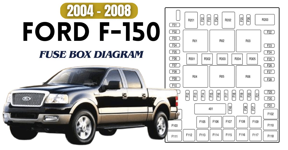
If you drive a 2004–2008 Ford F-150, you know these trucks are tough—but even the best can have small electrical hiccups, like a dead radio, a headlight out, or power windows that quit. Usually, a blown fuse is to blame.
Fuses protect your truck’s electronics by cutting power when something goes wrong. This guide shows you where the fuse boxes are, how to read the diagram, and how to replace fuses quickly—no jargon, just simple steps to get you back on the road.
Table of Contents
2004 Ford F-150 Fuse Box Diagram
The 2004 Ford F-150 holds two fuse boxes: Passenger Compartment Fuse Panel and Auxiliary Relay Box.
Passenger Compartment Fuse Panel
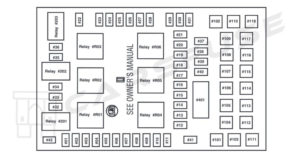
* Mini fuses/ ** Cartridge fuses.
| Fuse/RelayLocation | Fuse Amp Rating | Description |
| 1 | 10A* | Run/Accessory – Wipers, Instrument cluster |
| 2 | 20A* | Stop/Turn lamps, Speed control deactivate switch |
| 3 | 5A* | Power mirrors, Memory logic power, Memory seats, and pedals |
| 4 | 10A* | DVD battery power |
| 5 | 7.5A* | Keep alive memory for Powertrain Control Module (PCM) and climate control module |
| 6 | 15A* | Parklamps, BSM, Instrument panel illumination |
| 7 | 5A* | Radio (start signal) |
| 8 | 10A* | Heated mirrors, Switch indicator |
| 9 | — | Not used |
| 10 | 20A* | Trailer tow backup lamps relay (PCB1), Trailer tow park lamp relay (R201) |
| 11 | 10A* | A/C clutch, 4×4 solenoid |
| 12 | — | Not used |
| 13 | 10A* | Climate control module power |
| 14 | 10A* | Back-up lamp and DaytimeRunning Lamps (DRL) relay coil, A/C pressure switch, Brake-shift interlock solenoid, Heated PCV |
| 15 | 5A* | Overdrive cancel, Cluster, Brake-Shift Interlock (BSI) |
| 16 | 10A* | ABS module (Run/Start power) |
| 17 | 15A* | Fog lamp relay (R202) |
| 18 | 10A* | Run/Start feed – Flasher relay, Electrochromatic mirror, Heated seats, BSM, Compass, RSS (Reverse Sensing System) |
| 19 | 10A* | Restraints (Airbag module) |
| 20 | 15A* | PCM 4×4 power |
| 21 | 15A* | Cluster keep alive power |
| 22 | 10A* | Delayed accessory power for audio, power door lock switch, and moonroof switch illumination |
| 23 | 10A* | RH low beam headlamp |
| 24 | 15A* | Battery saver power for demand lamps |
| 25 | 10A* | LH low beam headlamp |
| 26 | 20A* | Horn relay (PCB3), Horn power |
| 27 | 5A* | Passenger Airbag Deactivation (PAD) warning lamp, Cluster airbag warning lamp, Cluster RUN/START power |
| 28 | 5A* | SecuriLock transceiver (PATS) |
| 29 | 15A* | PCM 4×4 power |
| 30 | — | Not used |
| 31 | 20A* | Radio power |
| 32 | 15A* | Vapor Management Valve (VMV), A/C clutch relay, Canister vent, Heated Exhaust Gas Oxygen(HEGO) sensors #11 and #21, CMCV, Mass Air Flow (MAF) sensor, VCT |
| 33 | 15A* | Shift solenoid, CMS #12 and #22 |
| 34 | 20A* | Fuel injectors and PCM power |
| 35 | 20A* | Instrument cluster high beam indicator, High beam headlamps |
| 36 | 10A* | Trailer tow right turn/stop lamps |
| 37 | 20A* | Rear power point |
| 38 | 25A* | Subwoofer power |
| 39 | 20A* | Instrument panel powerpoint |
| 40 | 20A* | Low beam headlamps, DRL |
| 41 | 20A* | Cigar lighter, Diagnostic connector power |
| 42 | 10A* | Trailer tow left turn/stop lamps |
| 101 | 30A** | Starter solenoid |
| 102 | 20A** | Ignition switch feed |
| 103 | 20A** | ABS valves |
| 104 | — | Not used |
| 105 | 30A** | Electric trailer brakes |
| 106 | 30A** | Trailer tow battery charge |
| 107 | 30A** | Power door locks (BSM) |
| 108 | 30A** | Passenger power seat |
| 109 | 30A** | Driver power seat, Adjustable pedals |
| 110 | — | Not used |
| 111 | 30A** | 4×4 relays |
| 112 | 40A** | ABS pump power |
| 113 | 30A** | Wipers and washer pump |
| 114 | 40A** | Heated backlite, Heated mirror power |
| 115 | — | Not used |
| 116 | 30A** | Blower motor |
| 117 | — | Not used |
| 118 | 30A** | Heated seats |
| 401 | 30A Circuit breaker | Power windows, Moonroof, Power-sliding backlite |
| R01 | Full ISO relay | Starter solenoid |
| R02 | Full ISO relay | Accessory delay |
| R03 | Full ISO relay | Hi-beam headlamps |
| R04 | Full ISO relay | Heated backlite |
| R05 | Full ISO relay | Trailer tow battery charge |
| R06 | Full ISO relay | Blower motor |
| R201 | Half ISO relay | Trailer tow park lamps |
| R202 | Half ISO relay | Fog lamps |
| R203 | Half ISO relay | PCM |
Auxiliary Relay Box
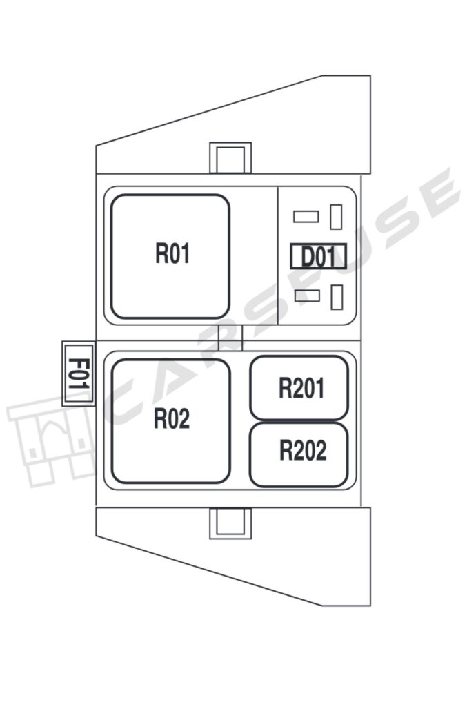
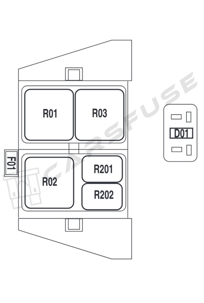
| Fuse/Relay location | Fuse amp rating | Description |
| F01 | 5A | Clockspring illumination |
| R01 | — | 4×4 CCW |
| R02 | — | 4×4 CW |
| R03 | — | Daytime Running Lamps (DRL) (if equipped, otherwise not used) |
| R201 | — | DRL |
| R202 | — | A/C clutch |
| D01 | — | A/C clutch diode |
2005 Ford F-150 Fuse Box Diagram
2005 F150 also contains two fuse box layouts: Passenger Compartment Fuse Panel and Auxiliary Relay Box.
Passenger Compartment Fuse Panel

* Mini fuses/ ** Cartridge fuses.
| Fuse/RelayLocation | Fuse AmpRating | Description |
| 1 | 10A* | Run/Accessory – Wipers, Instrument cluster, Audio for XL/STX |
| 2 | 20A* | Stop/Turn lamps, Brake on/off switch |
| 3 | 5A* | Power mirrors, Memory seats, and pedals |
| 4 | 10A* | DVD battery power, Power fold mirror |
| 5 | 7.5A* | Keep alive memory for Powertrain Control Module (PCM) and climate control module |
| 6 | 15A* | Parklamps, BSM, Instrument panel illumination |
| 7 | 5A* | Radio (start signal) |
| 8 | 10A* | Heated mirrors, Switch indicator |
| 9 | — | Not used |
| 10 | 20A* | Trailer tow back-up lamps relay(PCB1), Trailer tow park lamp relay(R201) |
| 11 | 10A* | A/C clutch, 4×4 solenoid |
| 12 | — | Not used |
| 13 | 10A* | Climate control module power, Flasher relay |
| 14 | 10A* | Back-up lamp and Daytime Running Lamps (DRL) relay coil, A/C pressure switch, Redundant speed control switch, Heated PCV (5.4L), Trailer tow back-up lamps relay coil, ABS, Reverse park aid, EC mirror |
| 15 | 5A* | Overdrive cancel, Cluster |
| 16 | 10A* | Brake-shift interlock solenoid |
| 17 | 15A* | Fog lamp relay (R202) |
| 18 | 10A* | Run/Start feed – Overhead power point, Electrochromatic mirror, Heated seats, BSM, Compass, RSS(Reverse Sensing System) |
| 19 | 10A* | Restraints (Airbag module) |
| 20 | 10A* | Battery feed for overhead powerpoint |
| 21 | 15A* | Cluster keep alive power |
| 22 | 10A* | Delayed accessory power for audio, power door lock switch, and moonroof switch illumination |
| 23 | 10A* | RH low beam headlamp |
| 24 | 15A* | Battery saver power for demand lamps |
| 25 | 10A* | LH low beam headlamp |
| 26 | 20A* | Horn relay (PCB3), Horn power |
| 27 | 5A* | Passenger Airbag Deactivation (PAD) warning lamp, Cluster airbag warning lamp, Cluster RUN /START power |
| 28 | 5A* | SecuriLock transceiver (PATS) |
| 29 | 15A* | PCM 4×4 power |
| 30 | 15A* | PCM 4×4 power |
| 31 | 20A* | Radio power |
| 32 | 15A* | Vapor Management Valve (VMV), A/C clutch relay, Canister vent, Heated Exhaust Gas Oxygen (HEGO) sensors#11 and #21, CMCV, Mass Air Flow(MAF) sensor, VCT, Heated PositiveCrankcase Ventilation (PCV) valve (4.2L engine), CID sensor (4.2L engine) |
| 33 | 15A* | Shift solenoid, CMS #12 and #22,4.6L/4.2L EGR |
| 34 | 20A* | Fuel injectors and PCM power, Intake Manifold Runner Control (4.2L engine) |
| 35 | 20A* | Instrument cluster high beam indicator, High beam headlamps |
| 36 | 10A* | Trailer tow right turn/stop lamps |
| 37 | 20A* | Rear power point |
| 38 | 25A* | Subwoofer power |
| 39 | 20A* | Instrument panel powerpoint |
| 40 | 20A* | Low beam headlamps, DRL |
| 41 | 20A* | Cigar lighter, Diagnostic connector power |
| 42 | 10A* | Trailer tow left turn/stop lamps |
| 101 | 30A** | Starter solenoid |
| 102 | 20A** | Ignition switch feed |
| 103 | 20A** | ABS valves |
| 104 | — | Not used |
| 105 | 30A** | Electric trailer brakes |
| 106 | 30A** | Trailer tow battery charge |
| 107 | 30A** | Power door locks (BSM) |
| 108 | 30A** | Passenger power seat |
| 109 | 30A** | Driver power seat, Adjustable pedals |
| 110 | — | Not used |
| 111 | 30A** | 4×4 relays |
| 112 | 40A** | ABS pump power |
| 113 | 30A** | Wipers and washer pump |
| 114 | 40A** | Heated backlite, Heated mirror power |
| 115 | — | Not used |
| 116 | 30A** | Blower motor |
| 117 | — | Not used |
| 118 | 30A** | Heated seats |
| 401 | 30A Circuit breaker | Power windows, Moonroof, Power-sliding backlite |
| R01 | Full ISO relay | Starter solenoid |
| R02 | Full ISO relay | Accessory delay |
| R03 | Full ISO relay | Hi-beam headlamps |
| R04 | Full ISO relay | Heated backlite |
| R05 | Full ISO relay | Trailer tow battery charge |
| R06 | Full ISO relay | Blower motor |
| R201 | Half ISO relay | Trailer tow park lamps |
| R202 | Half ISO relay | Fog lamps |
| R203 | Half ISO relay | PCM |
Auxiliary Relay Box
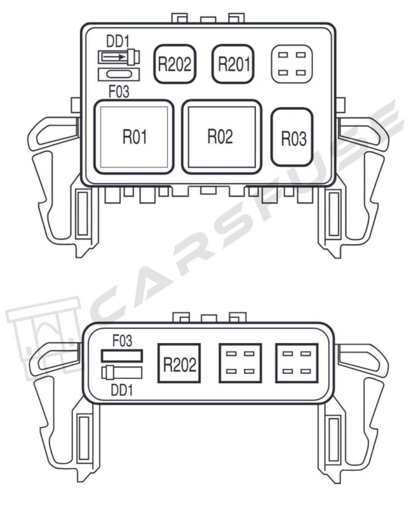
| Fuse/RelayLocation | Fuse Amp Rating | Description |
| F03 | 5A | Clockspring illumination |
| R01 | Full ISORelay | 4×4 CCW |
| R02 | Full ISORelay | 4×4 CW |
| R03 | 1⁄2 ISORelay | Daytime Running Lamps (DRL) high beam disable |
| R201 | Relay | DRL |
| R202 | Relay | A/C clutch |
| D01 | Diode | A/C clutch |
2006 Ford F-150 Fuse Box Diagram
You can also find two fuse box layouts in your 2006 F-150 and they are Passenger Compartment Fuse Panel and Auxiliary Relay Box.
Passenger Compartment Fuse Panel

* Mini fuses/ ** Cartridge fuses.
| Fuse/RelayLocation | Fuse AmpRating | Description |
| 1 | 10A* | Run/Accessory – Wipers, Instrument cluster, Audio for XL/STX |
| 2 | 20A* | Stop/Turn lamps, Brake on/off switch |
| 3 | 7.5A* | Power mirrors, Memory seats, and pedals |
| 4 | 10A* | DVD battery power, Power fold mirror |
| 5 | 7.5A* | Keep alive memory for Powertrain Control Module (PCM) and climate control module |
| 6 | 15A* | Parklamps, BSM, Instrument panel illumination |
| 7 | 5A* | Radio (start signal) |
| 8 | 10A* | Heated mirrors, Switch indicator |
| 9 | 20A* | Fuel pump relay, Fuel injectors, Intake manifold runner control(4.2L) |
| 10 | 20A* | Trailer tow back-up lamps relay(PCB1), Trailer tow park lamp relay(R201) |
| 11 | 10A* | A/C clutch, 4×4 solenoid |
| 12 | 5A* | PCM relay coil |
| 13 | 10A* | Climate control module power, Flasher relay |
| 14 | 10A* | Back-up lamp and Daytime Running Lamps (DRL) relay coil, A/C pressure switch, Redundant speed control switch, Heated PCV (5.4L), Trailer tow back-up lamps relay coil, ABS, Reverse park aid, EC mirror |
| 15 | 5A* | Overdrive cancel, Cluster |
| 16 | 10A* | Brake-shift interlock solenoid |
| 17 | 15A* | Fog lamp relay (R202) |
| 18 | 10A* | Run/Start feed – Overhead power point, Electrochromatic mirror, Heated seats, BSM, Compass, RSS(Reverse Sensing System) |
| 19 | 10A* | Restraints (Airbag module) |
| 20 | 10A* | Battery feed for overhead powerpoint |
| 21 | 15A* | Cluster keep alive power |
| 22 | 10A* | Delayed accessory power for audio, power door lock switch, and moonroof switch illumination |
| 23 | 10A* | RH low beam headlamp |
| 24 | 15A* | Battery saver power for demand lamps |
| 25 | 10A* | LH low beam headlamp |
| 26 | 20A* | Horn relay (PCB3), Horn power |
| 27 | 5A* | Passenger Airbag Deactivation (PAD) warning lamp, Cluster air bag warning lamp, Cluster RUN /START power |
| 28 | 5A* | SecuriLock transceiver (PATS), PCMIGN monitor |
| 29 | 15A* | PCM 4×4 power |
| 30 | 15A* | PCM 4×4 power |
| 31 | 20A* | Radio power |
| 32 | 15A* | Vapor Management Valve (VMV), A/C clutch relay, Canister vent, Heated Exhaust Gas Oxygen (HEGO) sensors #11 and #21, CMCV, Mass Air Flow (MAF) sensor, VCT, HeatedPositive Crankcase Ventilation (PCV) valve (4.2L engine), CID sensor (4.2L engine), 4.6L/4.2L EGR |
| 33 | 15A* | Shift solenoid, CMS #12 and #22,Ignition coils |
| 34 | 15A* | PCM power |
| 35 | 20A* | Instrument cluster high beam indicator, High beam headlamps |
| 36 | 10A* | Trailer tow right turn/stop lamps |
| 37 | 20A* | Rear power point |
| 38 | 25A* | Subwoofer power |
| 39 | 20A* | Instrument panel powerpoint |
| 40 | 20A* | Low beam headlamps, DRL |
| 41 | 20A* | Cigar lighter, Diagnostic connector power |
| 42 | 10A* | Trailer tow left turn/stop lamps |
| 101 | 30A** | Starter solenoid |
| 102 | 20A** | Ignition switch feed |
| 103 | 20A** | ABS valves |
| 104 | — | Not used |
| 105 | 30A** | Electric trailer brakes |
| 106 | 30A** | Trailer tow battery charge |
| 107 | 30A** | Power door locks (BSM) |
| 108 | 30A** | Passenger power seat |
| 109 | 30A** | Driver power seat, Adjustable pedals |
| 110 | — | Not used |
| 111 | 30A** | 4×4 relays |
| 112 | 40A** | ABS pump power |
| 113 | 30A** | Wipers and washer pump |
| 114 | 40A** | Heated backlite, Heated mirror power |
| 115 | — | Not used |
| 116 | 30A** | Blower motor |
| 117 | — | Not used |
| 118 | 30A** | Heated seats |
| 401 | 30A Circuit breaker | Power windows, Moonroof, Powe-sliding backlite |
| R01 | Full ISO relay | Starter solenoid |
| R02 | Full ISO relay | Accessory delay |
| R03 | Full ISO relay | Hi-beam headlamps |
| R04 | Full ISO relay | Heated backlite |
| R05 | Full ISO relay | Trailer tow battery charge |
| R06 | Full ISO relay | Blower motor |
| R201 | Half ISO relay | Trailer tow park lamps |
| R202 | Half ISO relay | Fog lamps |
| R203 | Half ISO relay | PCM |
Auxiliary Relay Box

| Fuse/RelayLocation | Fuse AmpRating | Description |
| F03 | 5A | Clockspring illumination |
| R01 | Full ISO Relay | 4×4 CCW |
| R02 | Full ISO Relay | 4×4 CW |
| R03 | 1⁄2 ISO Relay | Daytime Running Lamps (DRL) high beam disable |
| R201 | Relay | DRL |
| R202 | Relay | A/C clutch |
| D01 | Diode | A/C clutch |
2007 Ford F-150 Fuse Box Diagram
You will also find two fuse box layouts in the 2007 Ford F-150 series trucks. Passenger Compartment Fuse Panel and Auxiliary Relay box are the two accessible locations.
Passenger Compartment Fuse Panel

* Mini fuses/ ** Cartridge fuses.
| Fuse/RelayLocation | Fuse AmpRating | Description |
| 1 | 10A* | Run/Accessory – Wipers, Instrument cluster, Audio for XL/STX |
| 2 | 20A* | Stop/Turn lamps, Brake on/off switch, Hazard flashers |
| 3 | 7.5A* | Power mirrors, Memory seats, and pedals, Driver power seat |
| 4 | 10A* | DVD battery power, Power fold mirror |
| 5 | 7.5A* | Keep alive memory for Powertrain Control Module (PCM) and climate control module |
| 6 | 15A* | Parklamps, BSM, Instrument panel illumination |
| 7 | 5A* | Radio (start signal) |
| 8 | 10A* | Heated mirrors, Switch indicator |
| 9 | 20A* | Fuel pump relay, Fuel injectors, Intake manifold runner control(4.2L) |
| 10 | 20A* | Trailer tow backup lamps relay (PCB1), Trailer tow park lamp relay (R201) |
| 11 | 10A* | A/C clutch, 4×4 solenoid |
| 12 | 5A* | PCM relay coil |
| 13 | 10A* | Climate control module power, Flasher relay |
| 14 | 10A* | Back-up lamp and DaytimeRunning Lamps (DRL) relay coil, A/C pressure switch, Redundant speed control switch, Heated PCV (5.4L), Trailer tow back-up lamps relay coil, ABS, Reverse park aid, EC mirror, Navigation radio(reverse input) |
| 15 | 5A* | Overdrive cancel, Cluster, Traction control switch |
| 16 | 10A* | Brake-shift interlock solenoid |
| 17 | 15A* | Fog lamp relay (R202) |
| 18 | 10A* | Run/Start feed – Overhead power point, Electrochromatic mirror, Heated seats, BSM, Compass, RSS(Reverse Sensing System) |
| 19 | 10A* | Restraints (Airbag module), OCS |
| 20 | 10A* | Battery feed for overhead powerpoint |
| 21 | 15A* | Cluster keep alive power |
| 22 | 10A* | Delayed accessory power for audio, power door lock switch, and moon roof switch illumination |
| 23 | 10A* | RH low beam headlamp |
| 24 | 15A* | Battery saver power for demand lamps |
| 25 | 10A* | LH low beam headlamp |
| 26 | 20A* | Horn relay (PCB3), Horn power |
| 27 | 5A* | Passenger Airbag Deactivation(PAD) warning lamp, Cluster RUN/START power |
| 28 | 5A* | SecuriLock transceiver (PATS), PCM IGN monitor |
| 29 | 15A* | PCM 4×4 power |
| 30 | 15A* | PCM 4×4 power |
| 31 | 20A* | Radio power, Satellite radio module |
| 32 | 15A* | Vapor Management Valve (VMV), A/C clutch relay, Canister vent, Heated Exhaust Gas Oxygen(HEGO) sensors #11 and #21, CMCV, Mass Air Flow (MAF) sensor, VCT, Heated Positive Crankcase Ventilation (PCV) valve (4.2L engine), CID sensor (4.2L engine), 4.6L/4.2L EGR, Electronic fan clutch (4.6L/5.4L engines) |
| 33 | 15A* | Shift solenoid, CMS #12 and #22,Ignition coils |
| 34 | 15A* | PCM power |
| 35 | 20A* | Instrument cluster high beam indicator, High beam headlamps |
| 36 | 10A* | Trailer tow right turn/stop lamps |
| 37 | 20A* | Rear power point, Center console powerpoint |
| 38 | 25A* | Subwoofer power |
| 39 | — | Not used |
| 40 | 20A* | Low beam headlamps, DRL |
| 41 | — | Not used |
| 42 | 10A* | Trailer tow left turn/stop lamps |
| 101 | 30A** | Starter solenoid |
| 102 | 20A** | Ignition switch feed |
| 103 | 20A** | ABS valves |
| 104 | — | Not used |
| 105 | 30A** | Electric trailer brakes |
| 106 | 30A** | Trailer tow battery charge |
| 107 | 30A** | Power door locks (BSM) |
| 108 | 30A** | Passenger power seat |
| 109 | 30A** | Driver power seat, Adjustable pedals, Memory module (pedals, seat, mirror) |
| 110 | 20A** | Cigar lighter, Diagnostic connector power |
| 111 | 30A** | 4×4 relays |
| 112 | 40A** | ABS pump power |
| 113 | 30A** | Wipers and washer pump |
| 114 | 40A** | Heated backlite, Heated mirror power |
| 115 | 20A** | Not used (Spare) |
| 116 | 30A** | Blower motor |
| 117 | 20A** | Instrument panel powerpoint |
| 118 | 30A** | Heated seats |
| 401 | 30A Circuit breaker | Delayed accessory power: Power windows, Moon roof, Power-sliding backlite |
| R01 | Full ISO relay | Starter solenoid |
| R02 | Full ISO relay | Accessory delay |
| R03 | Full ISO relay | Hi-beam headlamps |
| R04 | Full ISO relay | Heated backlite |
| R05 | Full ISO relay | Trailer tow battery charge |
| R06 | Full ISO relay | Blower motor |
| R201 | Half ISO relay | Trailer tow park lamps |
| R202 | Half ISO relay | Fog lamps |
| R203 | Half ISO relay | PCM |
Auxiliary Relay Box
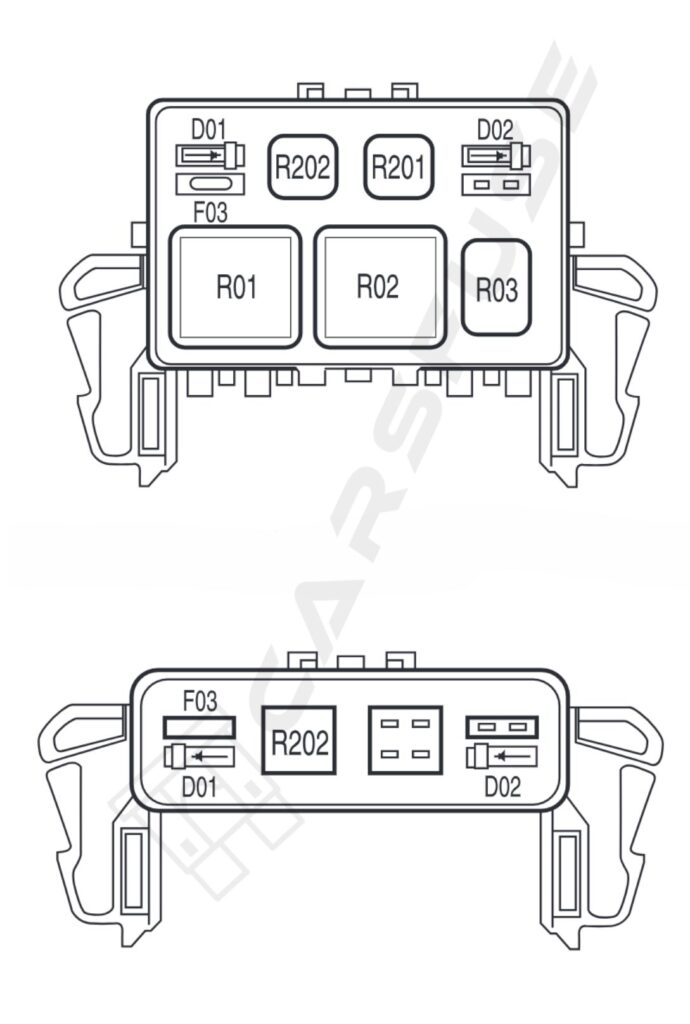
| Fuse/RelayLocation | Fuse AmpRating | Description |
| F03 | 5A | Clockspring illumination |
| R01 | Full ISORelay | 4×4 CCW |
| R02 | Full ISORelay | 4×4 CW |
| R03 | 1⁄2 ISORelay | Daytime Running Lamps (DRL) high beam disable |
| R201 | Relay | DRL |
| R202 | Relay | A/C clutch |
| D01 | Diode | A/C clutch |
| D02 | Diode | One Touch Integrated Start (OTIS) |
2008 Ford F-150 Fuse Box Diagram
Passenger compartment fuse panel/power distribution box and the Auxiliary Relay Box are the two fuse locations on the 2008 Ford F150.
Passenger compartment fuse panel/power distribution box
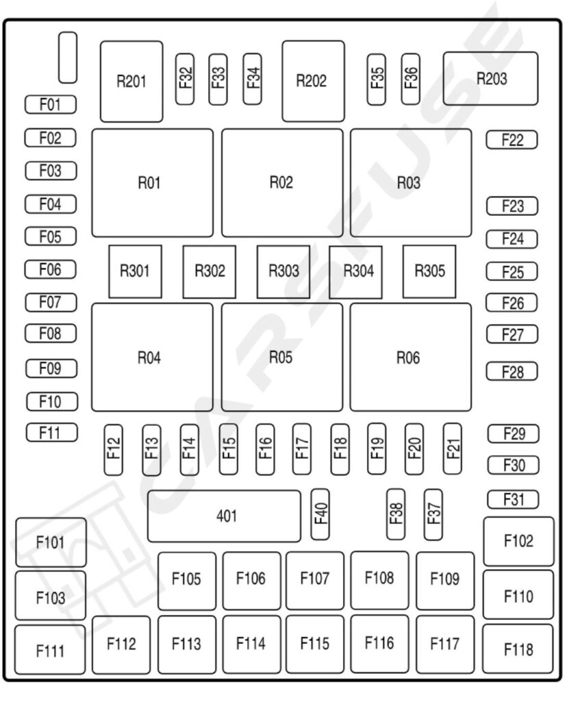
| Fuse/Relay Location | Fuse AmpRating | Description |
| F01 | 10A* | Run/Accessory – Wipers, Instrument cluster, Audio for XL/STX |
| F02 | 20A* | Stop/Turn lamps, ABS, T/T electric brake module, PCM (BOO signal), turn signal mirrors, CHMSL |
| F03 | 7.5A* | Power mirrors, Memory seats, and pedals |
| F04 | 10A* | DVD battery power, Power fold mirror |
| F05 | 7.5A* | Keep alive memory for PowertrainControl Module (PCM), and Climate control module |
| F06 | 15A* | Parklamps, Body Security Module (BSM), Instrument panel illumination |
| F07 | 5A* | Radio (start signal) |
| F08 | 10A* | Heated mirrors, Switch indicator |
| F09 | 20A* | Fuel pump relay, Fuel injectors, Injector sense |
| F10 | 20A* | Trailer tow backup lamps relay, Trailer tow park lamp relay |
| F11 | 10A* | A/C clutch, 4×4 solenoid |
| F12 | 5A* | PCM relay coil |
| F13 | 10A* | Climate control module power, Flasher relay |
| F14 | 10A* | Back-up lamp and DaytimeRunning Lamps (DRL) relay coil, A/C pressure switch, Redundant speed control switch, Heated PCV(5.4L), ABS |
| F15 | 5A* | Overdrive cancel, Cluster |
| F16 | 10A* | Brake-shift interlock solenoid |
| F17 | 15A* | Fog lamp relay |
| F18 | 10A* | Electrochromatic mirror, Heated seats, BSM, Compass, RSS (Reverse Sensing System), Power rail |
| F19 | 10A* | Restraints (Airbag module) |
| F20 | 10A* | Power rail |
| F21 | 15A* | Cluster keep alive power |
| F22 | 10A* | Delayed accessory power for audio, power door lock switch,and moon roof switch illumination |
| F23 | 10A* | RH low beam headlamp |
| F24 | 15A* | Battery saver power for demand lamps, Flex fuel |
| F25 | 10A* | LH low beam headlamp |
| F26 | 20A* | Horn |
| F27 | 5A* | Passenger Airbag Deactivation (PAD) warning lamp, Cluster airbag warning lamp |
| F28 | 5A* | SecuriLock transceiver (PATS), PCM IGN monitor |
| F29 | 15A* | PCM 4×4 power |
| F30 | 15A* | PCM 4×4 power |
| F31 | 20A* | Radio power, Satellite radio module |
| F32 | 15A* | Vapor Management Valve (VMV),A/C clutch relay, Canister vent,Heated Exhaust Gas Oxygen(HEGO) sensors #11 and #21, CMCV, Mass Air Flow (MAF) sensor, Variable Cam Timing (VCT), Heated Positive Crankcase Ventilation (PCV) valve (4.2L engine), CID sensor (4.2L engine), 4.6L/4.2L EGR |
| F33 | 15A* | Shift solenoid, CMS #12 and #22,Ignition coils |
| F34 | 15A* | PCM power, IMRC (4.2L) |
| F35 | 20A* | Instrument cluster high beam indicator, High beam headlamps, DRL disable relay |
| F36 | 10A* | Trailer tow right turn/stop lamps |
| 37 | 20A* | Rear power point |
| 38 | 25A* | Subwoofer power |
| 39 | — | Not used |
| 40 | 20A* | Low beam headlamps, DRL |
| 41 | — | Not used |
| 42 | 10A* | Trailer tow left turn/stop lamps |
| F101 | 30A** | Starter solenoid |
| F102 | 20A** | Ignition switch feed |
| F103 | 20A** | ABS valves |
| F104 | — | Not used |
| F105 | 30A** | Electric trailer brakes |
| F106 | 30A** | Trailer tow battery charge |
| F107 | 30A** | Power door locks (BSM) |
| F108 | 30A** | Passenger power seat |
| F109 | 30A** | Driver power seat, Adjustable pedals, Memory module (pedals, seats) |
| F110 | 20A** | Cigar lighter, Diagnostic connector power |
| F111 | 30A** | 4×4 motor relays |
| F112 | 40A** | ABS pump power |
| F113 | 30A** | Wipers and washer pump |
| F114 | 40A** | Heated backlite, Heated mirror power |
| F115 | 20A** | Moonroof |
| F116 | 30A** | Blower motor |
| F117 | 20A** | Instrument panel powerpoint |
| F118 | 30A** | Heated seats |
| 401 | 30A Circuit breaker | Delayed accessory power: Power windows, Power sliding backlite |
| R01 | Full ISO relay | Starter solenoid |
| R02 | Full ISO relay | Accessory delay |
| R03 | Full ISO relay | Hi-beam headlamps |
| R04 | Full ISO relay | Heated backlite |
| R05 | Full ISO relay | Trailer tow battery charge |
| R06 | Full ISO relay | Blower motor |
| R201 | Half ISO relay | Trailer tow park lamps |
| R202 | Half ISO relay | Fog lamps |
| R203 | Half ISO relay | PCM |
| R301 | Printed circuit board | Trailer tow backup lamps |
| R302 | — | Not used |
| R303 | Printed circuit board | Fuel pump |
| R304 | Printed circuit board | Battery saver |
| R305 | Printed circuit board | Horn |
Auxiliary Relay Box

| Fuse/RelayLocation | Fuse AmpRating | Description |
|---|---|---|
| F03 | 5A | Clockspring illumination |
| R01 | Full ISO Relay | 4×4 CCW |
| R02 | Full ISO Relay | 4×4 CW |
| R03 | 1⁄2 ISO Relay | Daytime Running Lamps (DRL) high beam disable |
| R201 | Relay | DRL |
| R202 | Relay | A/C clutch |
| D01 | Diode | A/C clutch |
| D02 | Diode | One Touch Integrated Start (OTIS) |
Tip: Some high-amperage fuses may look slightly different depending on the model year and trim. Always verify the fuse type before replacing.
Fuse Replacement Tips / Safety Precautions
- Always disconnect the negative battery terminal before removing fuses.
- Never replace a blown fuse with a higher amp rating — this can damage wiring or cause a fire.
- Use a fuse puller or needle-nose pliers for safety.
- Label replaced fuses for future reference.
Frequently Asked Questions (FAQs)
Why does the tail light fuse blow in an F-150?
Common causes include:
Short circuit: Damaged or frayed wires touching metal can overload the fuse.
Bad or wrong bulb: A faulty or incompatible bulb can draw too much power.
Faulty light switch: A broken switch can cause current spikes.
Wrong fuse: Using a fuse with too low amperage can make it blow even when everything else is fine.
Why does the brake light fuse blow in an F-150?
Common reasons:
Short circuit: Damaged or frayed wires touching metal can overload the fuse.
Bad brake bulbs: Faulty or burned-out bulbs can draw too much power.
Faulty brake light switch: A broken switch can cause current spikes.
Wrong fuse: Using a fuse with too low amperage can make it blow.
Why does the air conditioning fuse blow in an F-150?
Common reasons:
Short circuit: Damaged or frayed wires in the AC system can overload the fuse.
Bad compressor: A failing or seized compressor can draw too much power.
Fan problems: A stuck or worn condenser or cabin fan can cause excess current.
Faulty AC relay: A bad relay can disrupt electrical flow and blow the fuse.
Wrong fuse: Using a fuse with lower amperage than recommended can make it blow.
Why does the air conditioning relay fail in an F-150?
Common reasons:
Short circuits: Damaged or frayed wires can overload and burn the relay.
Compressor or component problems: Failing AC parts can draw too much current and damage the relay.
Relay wear: Frequent use over time can wear out the internal contacts and coil.

