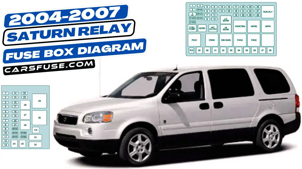
This article features fuse box diagrams for the Saturn Relay from 2004 to 2007. It explains where the fuse panels are located inside the minivan and details the purpose of each fuse and relay.
Table of Contents
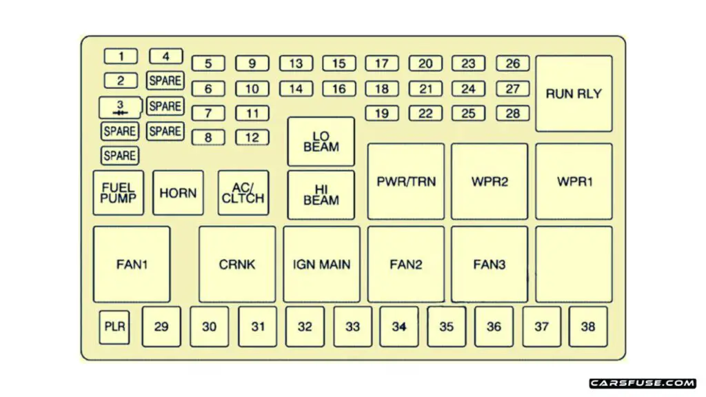
Engine Compartment

| Fuses | Usage |
|---|---|
| 1 | Right High-Beam |
| 2 | Fuel Pump |
| 3 | Diode |
| SPARE | Spare |
| SPARE | Spare |
| 4 | Left High-Beam |
| SPARE | Spare |
| SPARE | Spare |
| SPARE | Spare |
| 5 | Not Used |
| 6 | Air Conditioning Clutch |
| 7 | Horn |
| 8 | Left Low-Beam |
| 9 | Powertrain Control Module, Electronic Throttle Control |
| 10 | Not Used |
| 11 | Transmission Solenoid |
| 12 | Right Low-Beam |
| 13 | Anti-lock Brake System |
| 14 | Powertrain Control Module Ignition |
| 15 | Electronic Ignition |
| 16 | Fuel Injector |
| 17 | Climate Control, RPA, Cruise Control |
| 18 | Electronic Throttle Control |
| 19 | Engine Sensor, Evaporator |
| 20 | Airbag |
| 21 | Not Used |
| 22 | 2004, 2005: Emission, All-Wheel Drive 2006, 2007: Not Used |
| 23 | Auxiliary Power |
| 24 | Front Windshield Washer |
| 25 | AC/DC Inverter |
| 26 | Rear Blower |
| 27 | Front Blower |
| 28 | Front Windshield Wiper |
| J-Case Fuses | |
| PLR | Fuse Puller |
| 29 | Fan 1 |
| 30 | Starter Solenoid |
| 31 | Anti-lock Brake System Motor |
| 32 | Blank |
| 33 | Fan 2 |
| 34 | Front Blower High |
| 35 | Battery Main 3 |
| 36 | Rear Defogger |
| 37 | Battery Main 2 |
| 38 | 2004, 2005: Battery Main 1 2006, 2007: Spare |
| Relays | |
| RUN RLY | Starter |
| LO BEAM | Low-Beam |
| FUEL PUMP | Fuel Pump |
| HORN | Horn |
| AC/CLTCH | Air Conditioning Clutch |
| HI BEAM | High-Beam |
| PWR/TRN | Powertrain |
| WPR2 | Wiper 2 |
| WPR1 | Wiper 1 |
| FAN 1 | Fan 1 |
| CRNK | Crank |
| IGN MAIN | Ignition Main |
| FAN2 | Fan 2 |
| FAN 3 | Fan 3 |
| BLANK | Not Used |
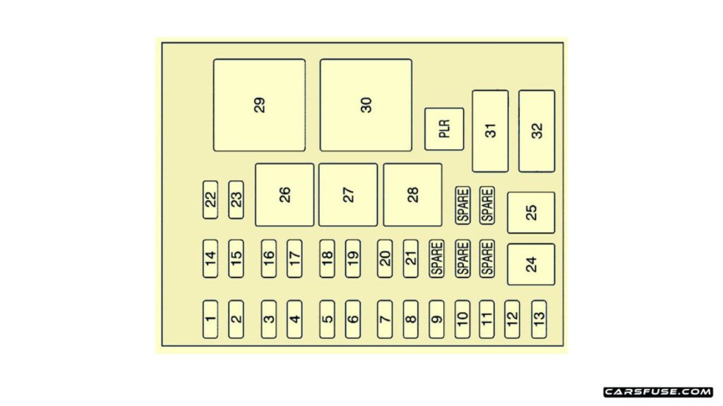
Passenger Compartment

| Fuses | Usage |
|---|---|
| PLR | Fuse Puller |
| 1 | Trunk, Door Locks |
| 2 | Electronic Level Control |
| 3 | Rear Wiper |
| 4 | Radio, DVD Player |
| 5 | Interior Lamps |
| 6 | OnStar |
| 7 | Keyless Entry Module |
| 8 | Cluster, Heating, Ventilation, Air Conditioning |
| 9 | Cruise Switch |
| 10 | Steering Wheel Illumination |
| 11 | Power Mirror |
| 12 | Stoplamp, Turn Lamps |
| 13 | Heated Seats |
| 14 | Blank |
| 15 | Electronic Level Control |
| 16 | Heated Mirror |
| 17 | Center High-Mounted Stoplamp, Back-up Lamps |
| 18 | Blank |
| 19 | Canister Vent Solenoid |
| 20 | Park Lamps |
| 21 | Power Sliding Door |
| 22 | Blank |
| 23 | Blank |
| 24 | Left Power Sliding Door |
| 25 | Right Power Sliding Door |
| Relays | |
| 26 | Blank |
| 27 | Blank |
| 28 | Park Lamps, Taillamps |
| 29 | Retained Accessory Power |
| 30 | Rear Defog |
| Circuit Breaker | |
| 31 | Power Seats |
| 32 | Power Window |
Next Post: 2012-2015 Lexus ES250 / ES350 / ES300h / ES350h (XV60/AVV60) fuse box diagram
Tom Smith is a passionate car mechanic and automotive enthusiast, specializing in the intricate world of car fuse boxes. With years of hands-on experience under the hood, he has earned a reputation as a reliable expert in his field. As the founder and content creator of the popular blog website 'carsfuse.com,' Tom has dedicated himself to sharing his extensive knowledge of car fuse boxes and electrical systems with the world.

