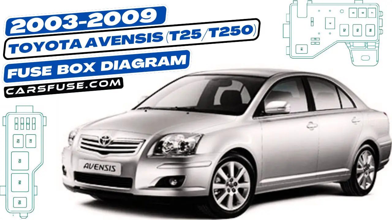
This article focuses on the second-generation Toyota Avensis (T25/T250) made between 2003 and 2009. It provides fuse box diagrams for models from 2003 to 2009, detailing where the fuse panels are located inside the car. It also explains the purpose of each fuse (fuse layout) and relay.
Table of Contents
Cigar lighter (power outlet) fuses in the Toyota Avensis are the fuses #9 “CIG” (Cigarette Lighter) and #16 “P/POINT” (Power Outlet) in the Instrument panel fuse box #1.
Engine Compartment
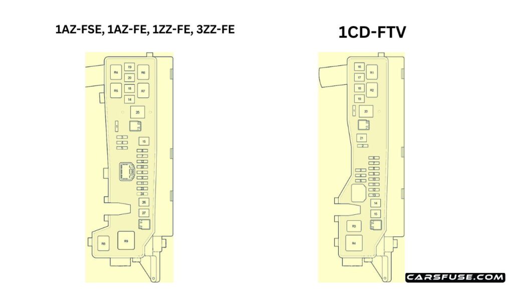
| № | Name | Amp | Circuit |
|---|---|---|---|
| 1 | – | – | – |
| 2 | VSC | 25 | 1CD-FTV: ABS, VSC |
| 2 | ABS | 25 | 1CD-FTV: ABS |
| 3 | – | – | – |
| 4 | – | – | – |
| 5 | – | – | – |
| 6 | ALT-S | 7.5 | Charging system |
| 7 | DCC | 30 | “ECU-B NO.2”, “DOME”, “RAD NO.2” fuses |
| 8 | AM2 | 30 | Starting system, “ST”, “IGN” fuses |
| 9 | HAZARD | 10 | Turn signal and hazard warning light |
| 10 | F-HTR | 25 | 1CD-FTV: Fuel heater |
| 11 | HORN | 15 | Horn |
| 12 | EFI | 20 | Multiport fuel injection system/sequential multiport fuel injection system, “EFI NO.1”, “EFI NO.2” fuses |
| 13 | PWR HTR | 25 | 1CD-FTV: Power heater |
| 14 | RR DEF | 30 | Rear windshield defogger |
| 15 | MAIN | 40 | Headlight cleaner, headlight, “H-LP HI LH”, “H-LP HI RH”, “H-LP LH”, “H-LP RH” fuses |
| 16 | AM1 NO.1 | 50 | 1CD-FTV: “ACC”, “CIG”, “RAD NO.1”, “ECU-B NO.1”, “FL P/W”, “FR P/W”, “RL P/W”, “RR P/W” |
| 17 | H/CLN | 30 | Headlight Cleaner |
| 18 | HTR | 40 | Air conditioner, heater |
| 19 | CDS | 30 | Electric cooling fan |
| 20 | RDI | 40 | 1CD-FTV, 1ZZ-FE, 3ZZ-FE: Electric cooling fan |
| 20 | RDI | 30 | 1AZ-FE, 1AZ-FSE: Electric cooling fan |
| 21 | VSC | 50 | 1CD-FTV: ABS, VSC |
| 21 | ABS | 40 | 1CD-FTV: ABS |
| 22 | IG2 | 15 | 1AZ-FSE, 1AZ-FE, 1ZZ-FE, 3ZZ-FE: Starting system, multiport fuel injection system/sequential multiport fuel injection system |
| 23 | THROTTLE | 10 | 1AZ-FSE, 1AZ-FE, 1ZZ-FE, 3ZZ-FE: Electronic throttle control system |
| 23 | ETCS | 10 | 1AZ-FSE, 1AZ-FE, 1ZZ-FE, 3ZZ-FE: Electronic throttle control system |
| 24 | A/F | 20 | 1AZ-FSE, 1AZ-FE: Air fuel ratio sensor |
| 25 | – | – | 1AZ-FSE, 1AZ-FE, 1ZZ-FE, 3ZZ-FE: – |
| 26 | – | – | 1AZ-FSE, 1AZ-FE, 1ZZ-FE, 3ZZ-FE: – |
| 27 | EM PS | 50 | 1ZZ-FE, 3ZZ-FE: Electric power steering |
| Relay | |||
| R1 | EFI MAIN | 1CD-FTV: Engine control unit | |
| R2 | EDU | 1CD-FTV: Engine control unit | |
| R3 | FAN NO.3 | 1CD-FTV: Electric cooling fan | |
| R4 | FAN NO.1 | Electric cooling fan | |
| R5 | FAN NO.2 | 1AZ-FSE, 1AZ-FE, 1ZZ-FE, 3ZZ-FE: Electric cooling fan | |
| R6 | – | 1AZ-FSE/ 1AZ-FE, 1ZZ-FE, 3ZZ-FE: – | |
| R7 | FAN NO.3 | 1AZ-FSE, 1AZ-FE, 1ZZ-FE, 3ZZ-FE: Electric cooling fan | |
| R8 | – | 1AZ-FSE/ 1AZ-FE, 1ZZ-FE, 3ZZ-FE: – | |
| R9 | EM PS | 1ZZ-FE, 3ZZ-FE: Electric power steering |
Additional Fuse Box
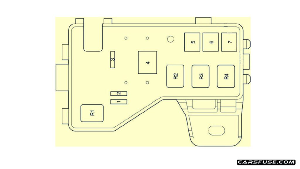
(1AZ-FSE, 1AZ-FE, 1ZZ-FE, 3ZZ-FE)
| № | Name | Amp | Circuit |
|---|---|---|---|
| 1 | EFI NO.1 | 10 | Multiport fuel injection system/sequential multiport fuel injection system |
| 2 | EFI NO.2 | 7.5 | Emission control system |
| 3 | VSC | 25 | ABS, VSC |
| 3 | ABS | 25 | ABS |
| 4 | ALT | 100 | 1ZZ-FE, 3ZZ-FE: “AM1 NO.1”, “H-LP CLN”, “ABS” (25A), “VSC” (25A), “ABS” (40A), “VSC” (50 A), “CDS”, “RDI”, “HTR”, “RR DEF”, “RR FOG”, “FR FOG”, “AM1”, “DOOR”, “STOP”, “OBD2”, “S/ROOF”, “PWR SEAT”, “P/POINT”, “TAIL”, “PANEL”, “RR WIP”, “ECU-IG”, “WIP”, “GAUGE2”, “GAUGEl”, “HTR” ,”S-HTR” fuses |
| 4 | ALT | 120 | 1AZ-FSE, 1AZ-FE: “AM1 NO.1”, “H-LP CLN”, “ABS” (25A), “VSC” (25A), “ABS” (40A), “VSC” (50 A), “CDS”, “RDI”, “HTR”, “RR DEF”, “RR FOG”, “FR FOG”, “AM1”, “DOOR”, “STOP”, “OBD2”, “S/ROOF”, “PWR SEAT’, “P/POINT”, “TAIL”, “PANEL”, “RR WIP”, “ECU-IG”, “WIP”, “GAUGE2”, “GAUGEl”, “HTR” ,”S-HTR” fuses |
| 5 | VSC | 50 | ABS, VSC |
| 5 | ABS | 40 | ABS |
| 6 | AM1 NO.1 | 50 | “PWR SEAT”, “FR DIC”, “FUEL OPN”, “ECU-B 1″, P-RR P/W”, “P-FR P/W”, “D-RR P/W”, “D-FR P/W” fuses |
| 7 | H-LP CLN | 30 | Headlight cleaner |
| Relay | |||
| R1 | INJ | Injector | |
| R2 | EFI | Engine control unit | |
| R3 | IG2 | Ignition | |
| R4 | A/F | Air fuel ratio sensor |
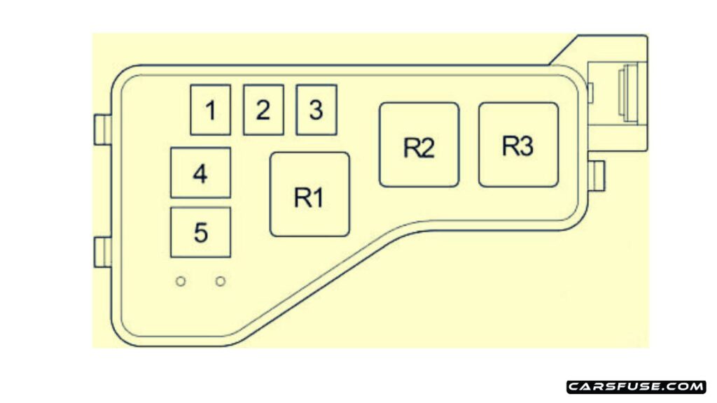
(1CD-FTV)
| № | Name | Amp | Circuit |
|---|---|---|---|
| 1 | – | – | – |
| 2 | HTR2 | 50 | Power heater |
| 3 | HTR1 | 50 | Power heater |
| 4 | GLOW | 80 | Glow plug |
| 5 | ALT | 140 | IG1 Relay, TAIL Relay, SEAT HTR Relay, “H-LP CLN”, “AM1 NO.1”, “RDI”, “CDS”, “VSC” (50A), “VSC” (25A), “ABS” (40A), “ABS” (25A), “H/CLN”, “RR DEF”, “GLOW”, “HTR NO.1”, “HTR NO.2”, “RFG HTR”, “AM1 NO.2”, “RR FOG”, “S/ROOF”, “STOP”, “P/POINT”, “FR FOG”, “OBD2”, “DOOR” fuses |
| Relay | |||
| R1 | – | – | |
| R2 | HTR2 | Power heater | |
| R3 | HTR1 | Power heater |
Relay Box
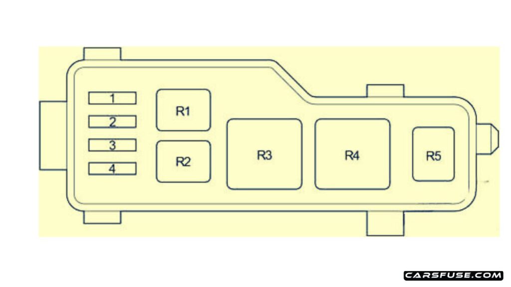
| № | Name | Amp | Circuit |
|---|---|---|---|
| 1 | H-LP HI LH | 10 | Left-hand headlight (high beam) |
| 2 | H-LP HI RH | 10 | Right-hand headlight (high beam), gauge and meters |
| 3 | H-LP LH | 15 | Left-hand headlight (low beam) |
| 4 | H-LP RH | 15 | Right-hand headlight (low beam) |
| Relay | |||
| R1 | HORN | Horn | |
| R2 | F-HTR | Fuel Heater | |
| R3 | H-LP | Headlight | |
| R4 | DIM | Dimmer | |
| R5 | FAN NO.2 | Electric cooling fan |
Passenger Compartment
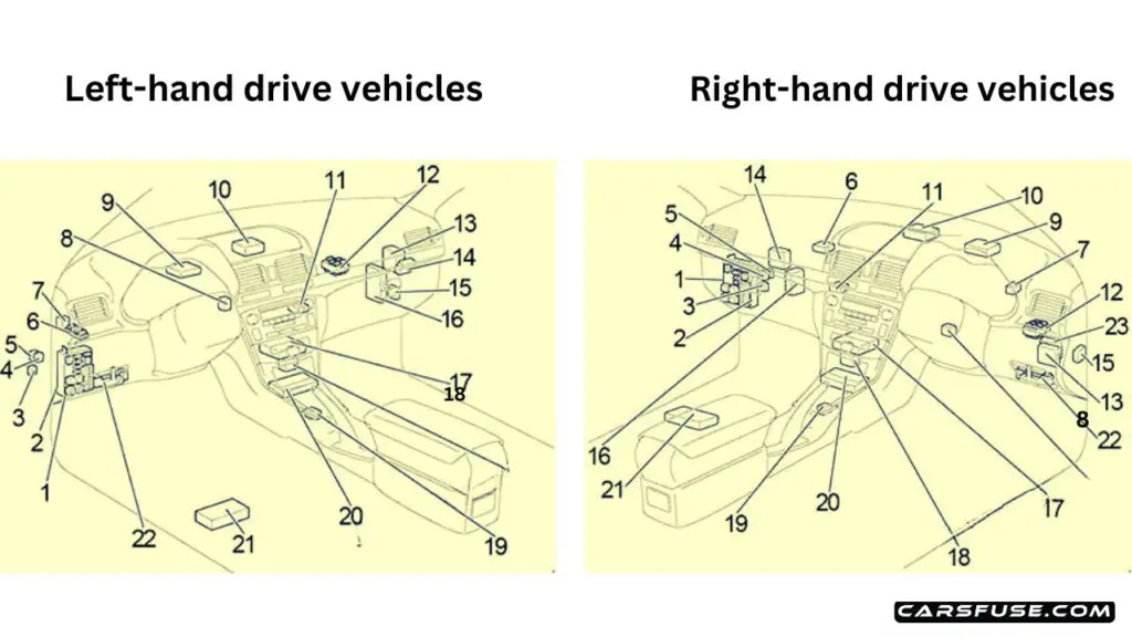
| 1. Fuse Box |
| 2. Integration Relay |
| 3. Circuit Opening Relay |
| 4. Rear Fog Light Relay |
| 5. Rear Window Defogger Relay |
| 6. Relay Box |
| 7. Turn Signal Flasher Relay |
| 8. Transponder Key Amplifier |
| 9. EPS ECU |
| 10. Transponder Key Computer |
| 11. Antenna Amplifier |
| 12. Junction Block |
| 13. Wiper Relay |
| 14. Door Control Receiver |
| 15. Headlight Beam Level Control ECU |
| 16. Engine and ECT ECU (A/T) Engine ECU (M/T) |
| 17.A/C Control Assembly |
| 18. Option Connector (Navigation ECU) |
| 19. Shift Lock Control ECU |
| 20. Airbag Sensor Assembly |
| 21. Navigation ECU |
| 22. Additional Fuse Box |
| 23. RHD:Theft Deterrent ECU |
Fuse box #1 diagram
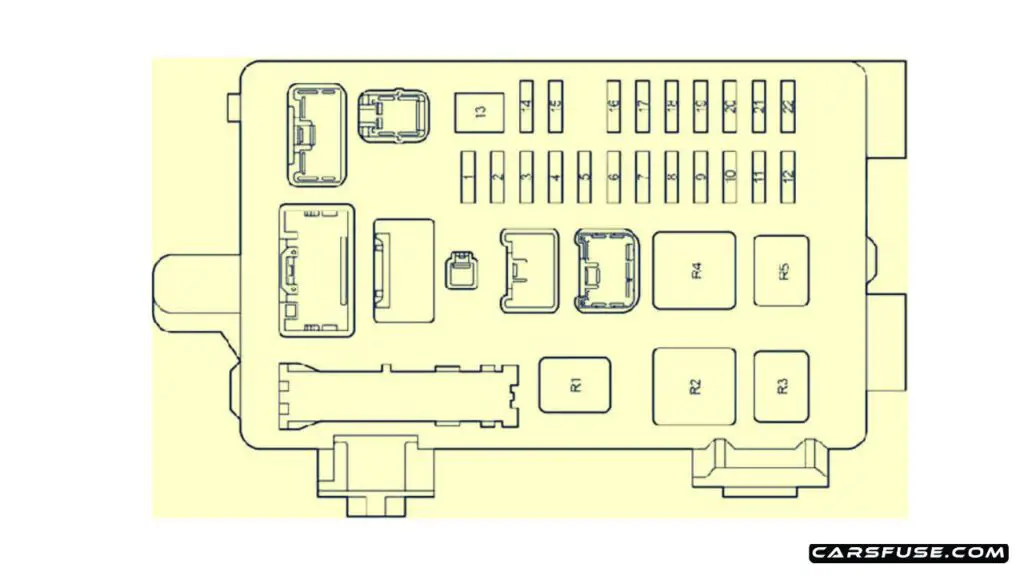
| № | Name | Amp | Circuit |
|---|---|---|---|
| 1 | IGN | 10 | SRS airbag system, gauge and meters, starting system, multiport fuel injection system/sequential multiport fuel injection system |
| 2 | S/ROOF | 20 | Sliding roof |
| 3 | RR FOG | 7.5 | Rear fog light |
| 4 | FR FOG | 15 | Front fog light, indicator light |
| 5 | AMI | 25 | Starting system, “CIG”, “RAD NO.1” fuses |
| 6 | PANEL | 7.5 | Instrument cluster lights, instrument panel lights, electronic controlled transmission, multi-information display, glove box light, console box light, headlight cleaner, front fog light, TOYOTA parking sssist |
| 7 | RR WIP | 20 | Rear wiper and washer |
| 8 | GAUGE2 | 7.5 | Back-up light, headlight leveling system, turn signal and hazard warning light |
| 9 | CIG | 15 | Cigarette Lighter |
| 10 | HTR | 10 | Seat heaters, air conditioning system |
| 11 | – | – | – |
| 12 | RAD NO.1 | 7.5 | Audio system, multi-information display, power rear view mirrors, gauge and meters, power outlet |
| 13 | PWR SEAT | 30 | Power seat |
| 14 | TAIL | 10 | Tail lights, parking lights, license plate lights, trunk light, automatic light control system, front fog light, rear fog light, combination meter |
| 15 | OBD2 | 7.5 | On-board diagnosis system |
| 16 | P/POINT | 15 | Power Outlet |
| 17 | DOOR | 25 | Power door lock system |
| 18 | WIP | 25 | Front wiper and washer, headlight cleaner |
| 19 | ECU-IG | 7.5 | Electric cooling fans, charging system, ABS, vehicle stability control system, electric power steering |
| 20 | S-HTR | 20 | Seat heaters |
| 21 | GAUGE1 | 10 | Switch illumination, multi-information display, integration relay, gauge and meters, shift lock control system, electronic controlled transmission, auto anti-glare inside rear view mirror, windshield wipers, parking brake |
| 22 | STOP | 15 | Stop light, shift lock control system, ABS, high mounted stoplight, multiport fuel injection system/sequential multiport fuel injection system |
| Relay | |||
| R1 | – | – | |
| R2 | HTR | Heater | |
| R3 | SEAT HTR | Seat Heater | |
| R4 | IG1 | Ignition | |
| R5 | TAIL | Taillight |
Additional Fuse Box
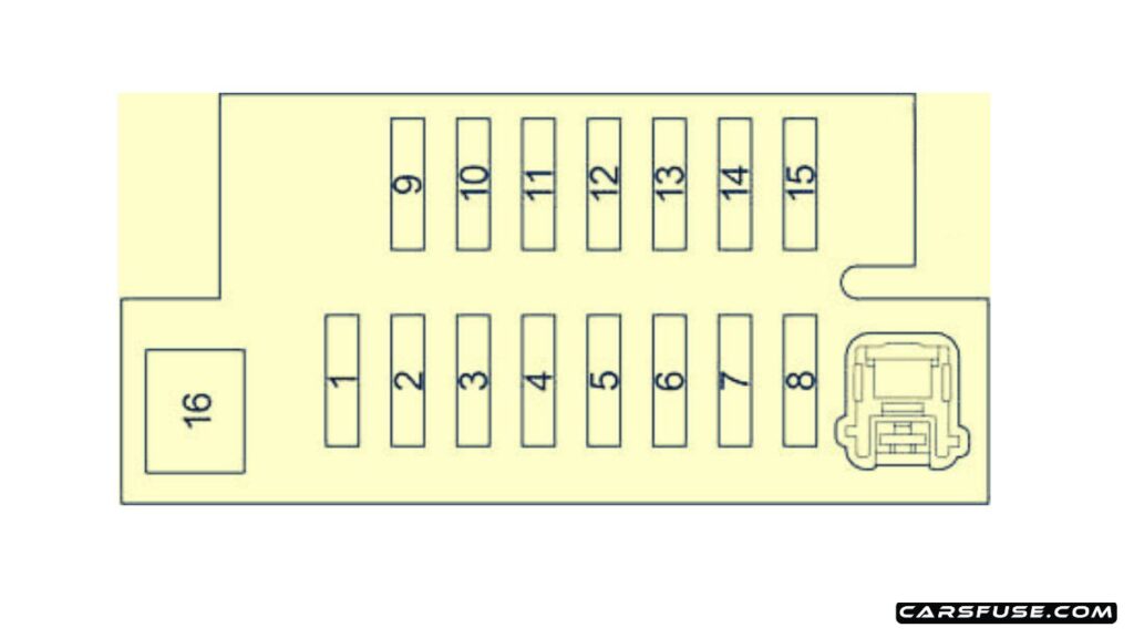
| № | Name | Amp | Circuit |
|---|---|---|---|
| 1 | – | – | – |
| 2 | P-RR P/W | 20 | Power window |
| 3 | P-FR P/W | 20 | Power window |
| 4 | D-RR P/W | 20 | Power window |
| 5 | D-FR P/W | 20 | Power window |
| 6 | ECU-B 1 | 7.5 | Multi-mode manual transmission |
| 7 | FUEL OPN | 10 | Fuel filler door opener |
| 8 | FR DIC | 20 | Front window deicer, “MIR FITR” fuse |
| 9 | – | – | – |
| 10 | DEF I/UP | 7.5 | Air conditioning system |
| 11 | ST | 7.5 | Multiport fuel injection system/sequential multiport fuel injection system, multi-information display, starting system |
| 12 | MIR HTR | 10 | Outside rear view mirror defogger |
| 13 | RAD NO.2 | 15 | Audio system, multi-information display |
| 14 | DOME | 7.5 | Interior light, personal lights, foot lights, door courtesy lights, trunk light, vanity lights |
| 15 | ECU-B 2 | 7.5 | Air conditioning system, wireless door lock control |
| 16 | PWR SEAT | 30 | Power seat |
Relay Box
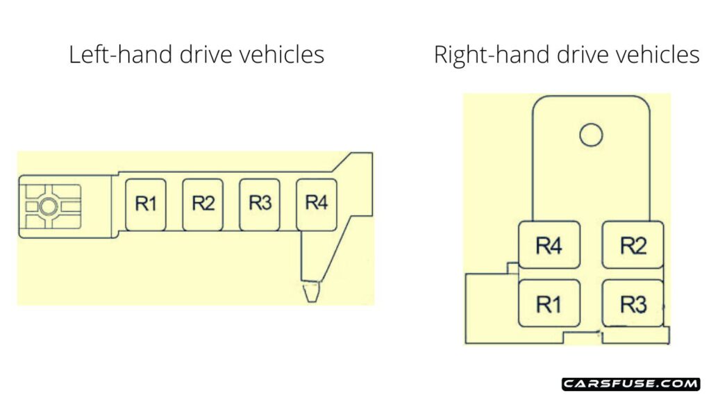
| № | Relay |
|---|---|
| R1 | Front window deicer (FR DEICER) |
| R2 | Power Outlet (P/POINT) |
| R3 | Front Fog Light (FR FOG) |
| R4 | Starter (ST) |
Next Post: 2007-2011 Toyota Camry (XV40) fuse box diagram
Tom Smith is a passionate car mechanic and automotive enthusiast, specializing in the intricate world of car fuse boxes. With years of hands-on experience under the hood, he has earned a reputation as a reliable expert in his field. As the founder and content creator of the popular blog website 'carsfuse.com,' Tom has dedicated himself to sharing his extensive knowledge of car fuse boxes and electrical systems with the world.

