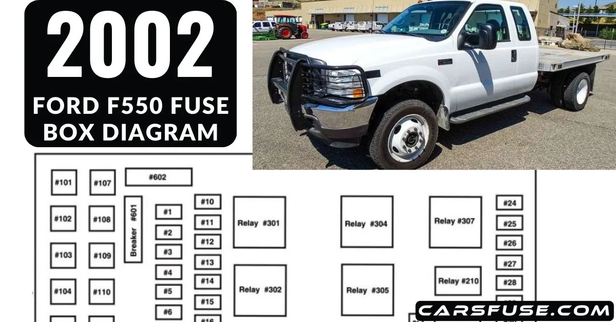
In this technical guide, we’ll discover the 2002 Ford F550 fuse box diagram, providing you with a comprehensive overview of each fuse’s purpose and its corresponding electrical system.
Table of Contents
Standard fuse amperage rating and color
| COLOR | |||||
| Fuse rating | Mini fuses | Standard fuses | Maxi fuses | Cartridge maxi fuses | Fuse link cartridge |
| 2A | Grey | Grey | — | — | — |
| 3A | Violet | Violet | — | — | — |
| 4A | Pink | Pink | — | — | — |
| 5A | Tan | Tan | — | — | — |
| 7.5A | Brown | Brown | — | — | — |
| 10A | Red | Red | — | — | — |
| 15A | Blue | Blue | — | — | — |
| 20A | Yellow | Yellow | Yellow | Blue | Blue |
| 25A | Natural | Natural | — | — | — |
| 30A | Green | Green | Green | Pink | Pink |
| 40A | — | — | Orange | Green | Green |
| 50A | — | — | Red | Red | Red |
| 60A | — | — | Blue | — | Yellow |
| 70A | — | — | Tan | — | Brown |
| 80A | — | — | Natural | — | Black |
2002 Ford F550 Fuse Box Diagram
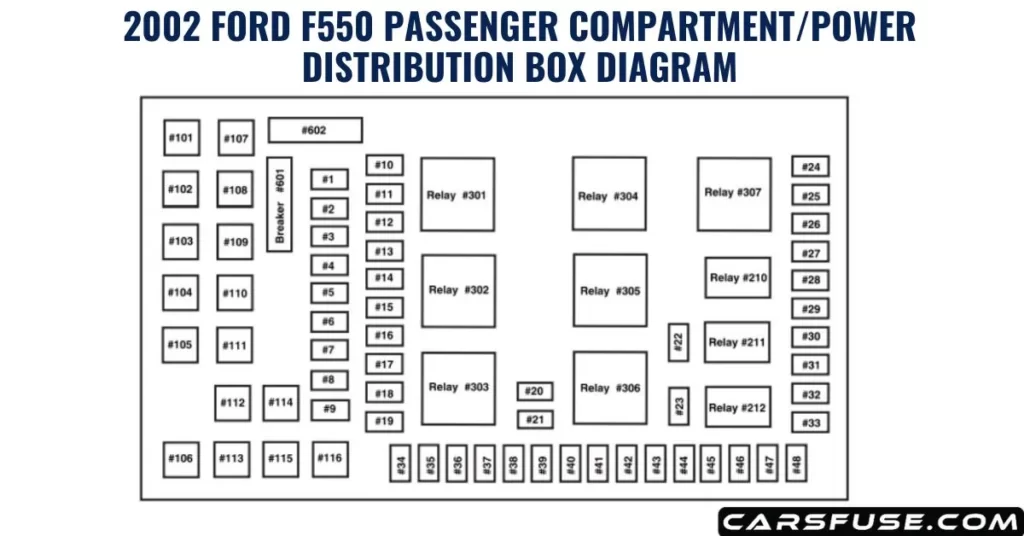
Passenger Compartment Fuse Panel/Power Distribution Box

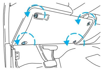
Located below and to the left of the steering wheel, in close proximity to the brake pedal, the fuse panel provides access to the fuses in your vehicle. To reach the fuses, it is necessary to remove the cover of the panel.
Removing the cover is a straightforward process. Simply rotate the panel fasteners counterclockwise. The fuse panel cover can be found below and to the left of the steering wheel, next to the brake pedal.
Once the panel cover is off, you’ll have full access to the fuses. Simply turn the panel fasteners counterclockwise to detach the fuse panel cover.

| Fuse/Relay Location | Fuse Amp Rating | Description |
| 1 | 15A* | Adjustable pedals |
| 2 | — | Not used |
| 3 | — | Not used |
| 4 | 20A* | Power point – instrument panel |
| 5 | — | Not used |
| 6 | 20A* | Trailer tow turn/stop relay |
| 7 | 30A* | High beam headlamps/Flash to pass |
| 8 | — | Not used |
| 9 | — | Not used |
| 10 | 10A* | A/C clutch |
| 11 | 20A* | Radio (main) |
| 12 | 20A* | Cigar lighter / OBD II |
| 13 | 5A* | Power mirrors/switches |
| 14 | 15A* | Daytime running lamps (DRL) |
| 15 | — | Not used |
| 16 | — | Not used |
| 17 | 15A* | Exterior lamps |
| 18 | 20A* | Turn lamps/Brake on-off switch (high) |
| 19 | 10A* | Body security module/4×4 module |
| 20 | — | Not used |
| 21 | — | Not used |
| 22 | 20A* | Engine control |
| 23 | 20A* | Engine control (gasoline engine only) |
| 24 | 15A* | Not used (spare) |
| 25 | 10A* | 4-Wheel Anti-lock Brake System (4WABS) module |
| 26 | 10A* | Air bags |
| 27 | 15A* | Ignition switch Run feed |
| 28 | 10A* | EATC module/Front blower relay coil |
| 29 | 10A* | Customer access |
| 30 | 15A* | Highbeam headlamps |
| 31 | 15A* | Clutch interlock switch (manual transmissions only), Transmission range sensor (automatic transmissions only) then to starter relay coil (all transmissions) |
| 32 | 5A* | Radio (start) |
| 33 | 15A* | Front wiper |
| 34 | 10A* | Brake on-off switch |
| 35 | 10A* | Instrument cluster |
| 36 | 10A* | PCM Keep-Alive |
| 37 | 15A* | Horn |
| 38 | 20A* | Trailer tow park lamps and backup lamps |
| 39 | — | Not used |
| 40 | 20A* | Fuel pump |
| 41 | 10A* | Instrument cluster |
| 42 | 15A* | Delayed accessory |
| 43 | 10A* | Fog lamps |
| 44 | — | Not used |
| 45 | 10A* | Ignition switch Run/Start feed |
| 46 | 10A* | Left-hand lowbeam |
| 47 | 10A* | Left-hand low beam |
| 48 | — | Not used |
| 101 | 30A** | Trailer tow electric brake |
| 102 | 30A** | Door locks/Body security module |
| 103 | 50A** | Ignition switch |
| 104 | — | Not used |
| 105 | 30A** | Injector driver module (Diesel engine only) |
| 106 | 30A** | Front wiper main |
| 107 | 40A** | Front blower motor |
| 108 | — | Not used |
| 109 | 30A** | Heated seats |
| 110 | 50A** | Ignition switch |
| 111 | 30A** | 4WD/Shift on the fly |
| 112 | 30A** | Left-hand power seats |
| 113 | 30A** | Starter motor |
| 114 | 30A** | Right-hand power seats |
| 115 | 20A** | Trailer tow battery charge |
| 116 | 30A** | Ignition switch |
| 601 | 30A CB*** | Door window motors |
| 602 | 60A** | 4WABS module |
| 210 | — | Not used |
| 211 | — | Not used |
| 212 | — | Not used |
| 301 | — | Front blower motor relay |
| 302 | — | Powertrain (EEC) relay |
| 303 | — | Injector driver module relay (Diesel engine only) |
| 304 | — | Not used |
| 305 | — | Trailer tow battery charge relay |
| 306 | — | Delayed accessory relay |
| 307 | — | Starter relay |
| * Mini Fuses ** Maxi Fuses ***Circuit Breaker | ||
Conclusion
To maintain a reliable and efficient electrical system in your 2002 Ford F550 heavy-duty truck, understanding its fuse box diagram is crucial. Knowing the layout and purpose of each fuse enables you to troubleshoot and address electrical issues promptly.
Always prioritize safety during the process. Exercise caution when working with electrical components and follow the manufacturer’s guidelines for fuse replacement.
If you have any uncertainties about the fuse box or the vehicle’s electrical system, consult the owner’s manual or seek assistance from a professional to ensure proper handling.
Tom Smith is a passionate car mechanic and automotive enthusiast, specializing in the intricate world of car fuse boxes. With years of hands-on experience under the hood, he has earned a reputation as a reliable expert in his field. As the founder and content creator of the popular blog website 'carsfuse.com,' Tom has dedicated himself to sharing his extensive knowledge of car fuse boxes and electrical systems with the world.

