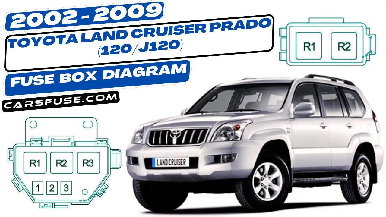
The third-generation Toyota Land Cruiser Prado (120/J120) was manufactured from 2002 to 2009. If you’re looking for fuse box diagrams for these model years (2002-2009), you can find them here. These diagrams show you where the fuse panels are located inside the car and provide details about what each fuse is assigned to control.
Table of Contents
Cigar lighter (power outlet) fuses in the Toyota Land Cruiser Prado are the fuses #12 “PWR OUTLET” and #24 “CIG” in the Instrument panel fuse box.
Fuse Box Location
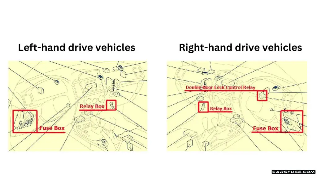
Passenger compartment: The fuse box is located on the driver’s side of the instrument panel, behind the cover.
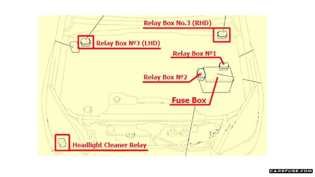
Engine Compartment
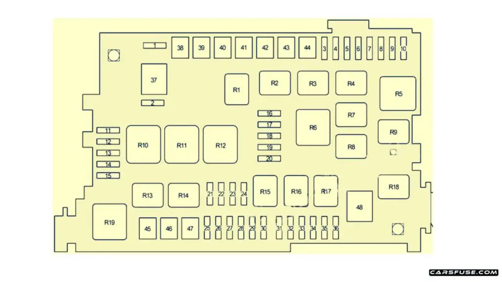
| Fuse Number | Name | Fuse Amp | Circuit |
|---|---|---|---|
| 1 | SPARE | 10 | Spare fuse |
| 2 | SPARE | 15 | Spare fuse |
| 3 | CDS FAN | 20 | Electric cooling fan |
| 4 | RR A/C | 30 | Rear cooler system |
| 5 | MIR HEATER | 10 | Outside rear view mirror heaters |
| 6 | STOP | 10 | Stop lights, high mounted stop light, shift lock control system, anti-lock brake system, active traction control system, vehicle stability control system, rear height control air suspension |
| 7 | – | – | – |
| 8 | FR FOG | 15 | Front fog lights |
| 9 | VISCUS | 7.5 | Viscous heater |
| 10 | OBD | 7.5 | On-board diagnosis system |
| 11 | HEAD (LO RH) | 10 | Right-hand headlight (low beam) |
| 12 | HEAD (LO LH) | 10 | Left-hand headlight (low beam) |
| 13 | HEAD (HI RH) | 10 | Right-hand headlight (high beam) |
| 14 | HEAD (HI LH) | 10 | Left-hand headlight (high beam) |
| 15 | EFI NO.2 | 10 | 2 O2 sensor and Air flow meter |
| 16 | HEATER NO.2 | 7.5 | Air conditioning system |
| 17 | DEFOG | 30 | Rear window defogger |
| 18 | AIRSUS NO.2 | 10 | Rear height control air suspension system |
| 19 | FUEL HEATER | 20 | Fuel heater |
| 20 | SEAT HEATER | 20 | Seat heater |
| 21 | DOME | 10 | Interior lights, personal lights, wireless remote control system, ignition switch light, door courtesy lights |
| 22 | RADIO NO.1 | 20 | Audio system |
| 23 | ECU-B | 10 | Anti-lock brake system, active traction control system, vehicle stability control system, air conditioning system, cool box, power windows |
| 24 | ECU-B NO.2 | 10 | Multiplex communication system |
| 25 | – | – | Short pin |
| 26 | ALT-S | 7.5 | Charging system |
| 27 | – | – | – |
| 28 | HORN | 10 | Horns |
| 29 | A/F HEATER | 15 | A/F sensor |
| 29 | F/PMP | 15 | 1KD-FTV: Fuel pump |
| 30 | TRN-HAZ | 15 | Turn signal lights, emergency flashers |
| 31 | ETCS | 10 | Multiport fuel injection system/sequential multiport fuel injection system |
| 32 | EFI | 20 | Electronically controlled fuel pump, fuel pump, multiport fuel injection system/sequential multiport fuel injection system |
| 32 | EFI | 25 | 1KD-FTV: Electronically controlled fuel pump, fuel pump, multiport fuel injection system/sequential multiport fuel injection system |
| 33 | D FR P/W | 20 | Driver’s power window |
| 34 | DR/LCK | 25 | Power door lock system |
| 35 | – | – | – |
| 36 | RADIO NO.2 | 30 | Audio system |
| 37 | ALT | 120 | without PTC: Defog relay, ignition relay, “HEATER”, “CDS FAN”, “AM1”, “J/B”, “VISCUS”, “OBD”, “MIR HEATER”, “STOP”, “FR FOG”, “AIRSUS”, “RR A/C” and “STOP” fuses |
| 37 | ALT | 140 | with PTC: Defog relay, ignition relay, “HEATER”, “CDS FAN”, “AM1”, “J/B”, “VISCUS”, “OBD”, “MIR HEATER”, “STOP”, “FR FOG”, “PTC-1”, “PTC-2”, “PTC-3”, “AIRSUS”, “RR A/C” and “STOP” fuses |
| 38 | HEATER | 50 | Air conditioning system |
| 39 | AIRSUS | 50 | Rear height control air suspension |
| 40 | AM1 | 50 | All components in “ACC”, “CIG”, “IG1”, “IG1 NO.2”, “ECU-IG”, “FR WIP-WSH”, “RR WIP”, “RR WSH”, “DIFF”, “TEMS” and “STA” fuses |
| 41 | PTC-1 | 40 | Viscous heater |
| 42 | J/B | 50 | All components in “PWR OUTLET”, “P FR P/W”, “P RR P/W”, “D RR P/W”, “D P/SEAT”, “P P/SEAT”, “POWER”, “TAIL” and “PANEL” fuses |
| 43 | PTC-2 | 40 | Viscous heater |
| 44 | PTC-3 | 40 | Viscous heater |
| 45 | ABS MTR | 40 | Anti-lock brake system, active traction control system, vehicle stability control system |
| 46 | AM2 | 30 | Starter system, “IGN”, “GAUGE” and “SRS” fuses |
| 47 | ABS SOL | 30 | without the vehicle stability control system: Anti-lock brake system |
| 47 | ABS SOL | 50 | with the vehicle stability control system: Anti-lock brake system, active traction control system, vehicle stability control system |
| 48 | GLOW | 80 | Engine glow system |
| Relay | |||
| R1 | Electric cooling fan (CDS FAN) | ||
| R2 | Accessory (ACC CUT) | ||
| R3 | Fog light | ||
| R4 | Starter (STA) | ||
| R5 | Ignition (IG) | ||
| R6 | Heater | ||
| R7 | Air conditioner compressor clutch (MG CLT) | ||
| R8 | – | ||
| R9 | Rear windshield defogger (DEFOG) | ||
| R10 | Anti-lock brake system (ABS MTR) | ||
| R11 | TRC MTR | ||
| R12 | Anti-lock brake system (ABS SOL) | ||
| R13 | Downhill Assist Control system (DAC) | ||
| R14 | Circuit opening Relay (C/OPN) or EDU | ||
| R15 | – | ||
| R16 | EFI | ||
| R17 | Air fuel ratio sensor (A/F HEATER) | ||
| R18 | Fuel pump | ||
| R19 | Headlight (HEAD) |
Relay Box No.1
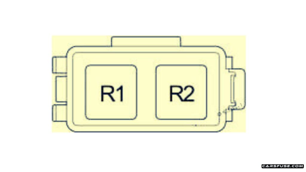
| Fuse Number | Relay |
|---|---|
| R1 | Starter (STA) |
| R2 | Glow system (GLOW) |
Relay Box No.2
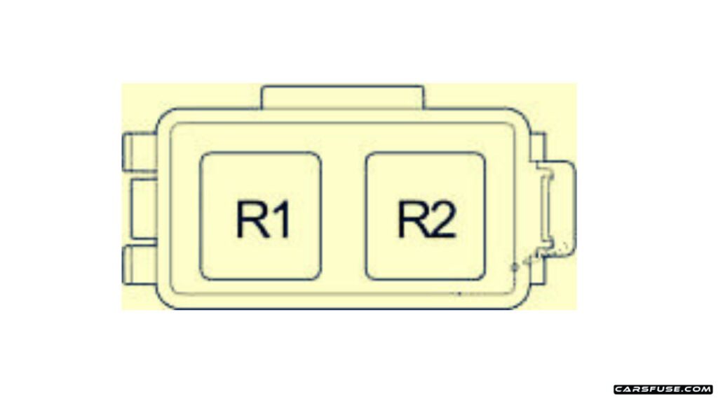
| Fuse Number | Relay |
|---|---|
| R1 | Air suspension (AIR SUS) |
| R2 | Dimmer (with Daytime Running Light) |
Relay Box No.3
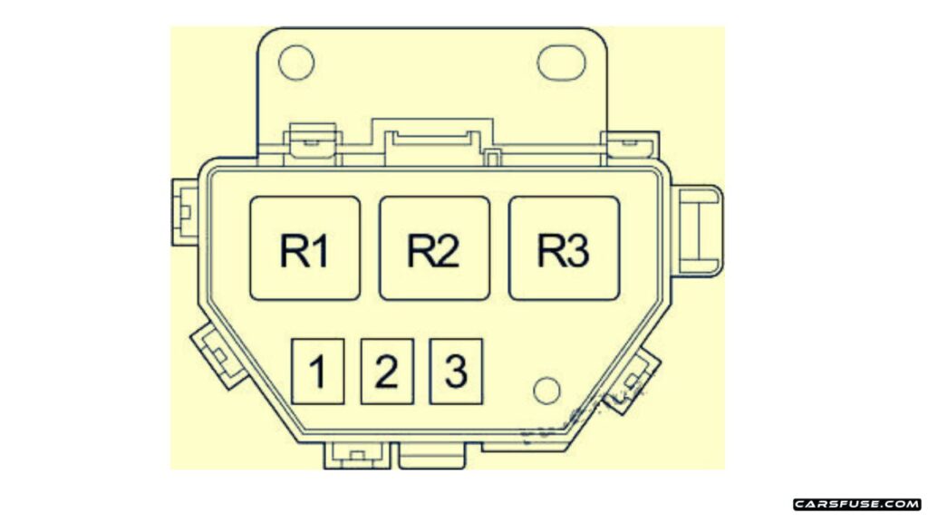
| Fuse Number | Relay |
|---|---|
| R1 | PTC NO.1 |
| R2 | PTC NO.2 |
| R3 | PTC NO.3 |
Passenger Compartment
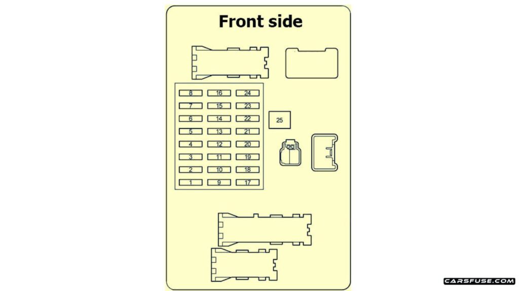
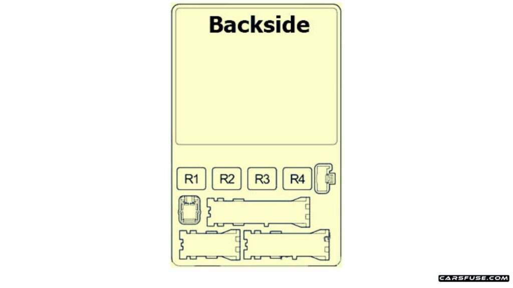
| Fuse Number | Name | Fuse Amp | Circuit |
|---|---|---|---|
| 1 | IGN | 10 | Electronically controlled fuel pump, multiport fuel injection system/sequential multiport fuel injection system, anti-lock brake system, active traction control system, vehicle stability control system |
| 2 | SRS | 10 | SRS airbags |
| 3 | GAUGE | 7.5 | Gauges and meters |
| 4 | ST2 | 7.5 | Multiport fuel injection system/sequential multiport fuel injection system |
| 5 | FR WIP-WSH | 30 | Windshield wipers and washer |
| 6 | TEMS | 20 | Toyota electronic modulated suspension |
| 7 | DIFF | 20 | Rear differential lock system, center differential lock system |
| 8 | RR WIP | 15 | Rear window wiper |
| 9 | – | – | – |
| 10 | D P/SEAT | 30 | LHD: Driver’s power seat |
| 10 | P P/SEAT | 30 | RHD: Front passenger’s power seat |
| 11 | P P/SEAT | 30 | LHD: Front passenger’s power seat |
| 11 | D P/SEAT | 30 | RHD: Driver’s power seat |
| 12 | PWR OUTLET | 15 | Power outlets |
| 13 | IG1 NO.2 | 10 | Air conditioning system, cool box |
| 14 | RR WSH | 15 | Rear window washer |
| 15 | ECU-IG | 10 | Shift lock control system, power windows, anti-lock brake system, active traction control system, vehicle stability control system, air conditioning system, electric moon roof, power outlets |
| 16 | IG1 | 10 | Anti-lock brake system, active traction control system, vehicle stability control system, air conditioning system, charging system, rear window defogger, back-up lights, turn signal lights, emergency flashers |
| 17 | STA | 7.5 | Electronically controlled fuel pump |
| 18 | P FR P/W | 20 | Front passenger’s power window |
| 19 | P RR P/W | 20 | LHD: Rear passenger’s power window |
| 19 | D RR P/W | 20 | RHD: Rear passenger’s power window |
| 20 | D RR P/W | 20 | LHD: Rear passenger’s power window |
| 20 | P RR P/W | 20 | RHD: Rear passenger’s power window |
| 21 | PANEL | 10 | Instrument panel lights |
| 22 | TAIL | 10 | Tail lights, license plate lights, parking lights |
| 23 | ACC | 7.5 | Electronically controlled automatic transmission system, power outlets, outside rear view mirrors, audio system |
| 24 | CIG | 10 | Cigarette lighter |
| 25 | POWER | 30 | Power windows, electric moon roof |
| Relay | |||
| R1 | Horn | ||
| R2 | Tail lights | ||
| R3 | Power relay | ||
| R4 | Accessory socket (ACC SKT) |
Relay Box
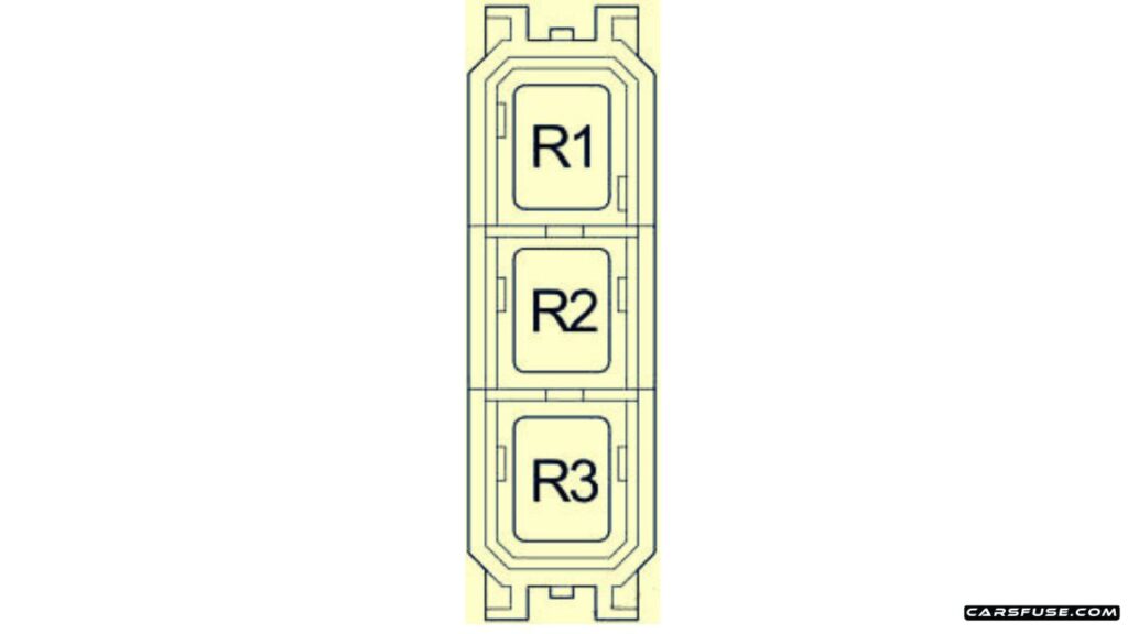
| Fuse Number | Relay |
|---|---|
| R1 | Panel relay |
| R2 | Back-up lights (BK/UP LP) |
| R3 | Outside rear view mirror heaters (MIR HTR) |
Next Post: 2014-2018 Toyota HiAce (H200) fuse box diagram
Tom Smith is a passionate car mechanic and automotive enthusiast, specializing in the intricate world of car fuse boxes. With years of hands-on experience under the hood, he has earned a reputation as a reliable expert in his field. As the founder and content creator of the popular blog website 'carsfuse.com,' Tom has dedicated himself to sharing his extensive knowledge of car fuse boxes and electrical systems with the world.

