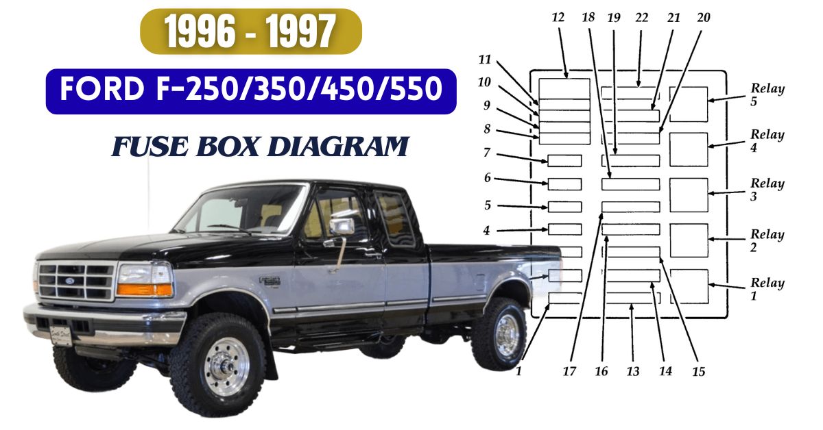
The Ford F-250, F-350, F-450, and F-550 trucks from 1996 and 1997 are known for their strength and reliability. Like any vehicle, they rely on a well-organized fuse box system to power and protect various electrical components.
This guide provides clear fuse box diagrams and explanations to help you locate, identify, and replace fuses when needed.
Table of Contents
1996 Ford F-250/350/450/550 Fuse Box Diagram
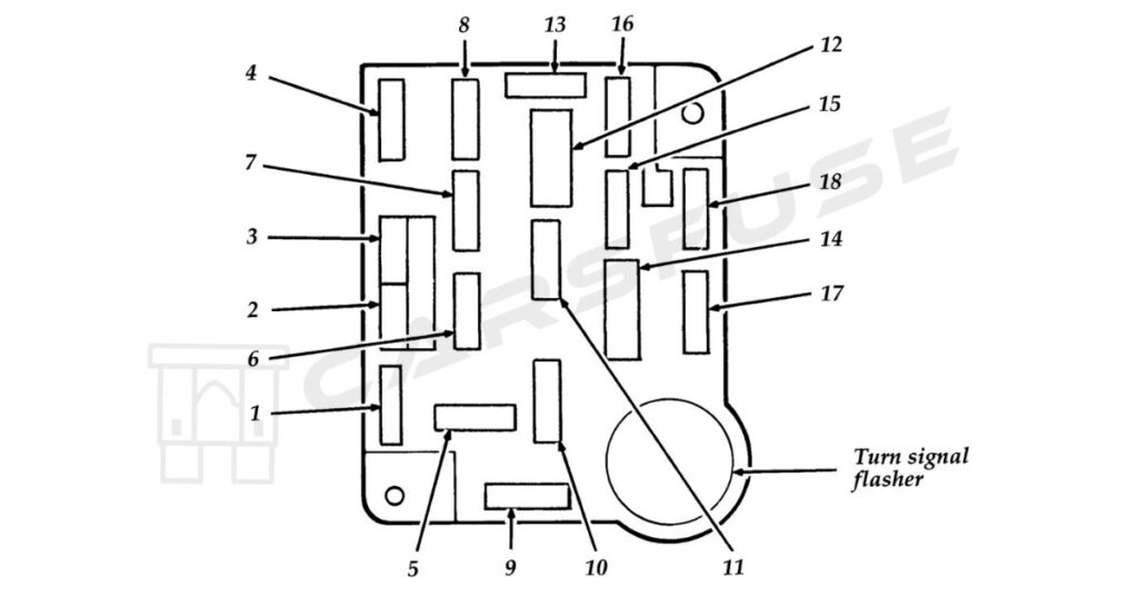
The Ford Superduty models (F-250, F-350, F-450 and F-550) built in the year 1996 feature two fuse box layouts: Instrument Panel Fuse Box and Engine Compartment Fuse Box.
Instrument Panel Fuse Box

| Fuse/CB Loe. | Fuse Amp. Rating | Description |
| 1 | 30 Amp | • Heater IAir conditioner blower |
| 2 | 30 Amp | • Wiper / Washer |
| 3 | 3 Amp | • Idle position switch (Diesel) |
| 4 | 15 Amp | • Exterior lamps • Instrument illumination • Trailer exterior lamp relay • Warning buzzer Ichime module |
| 5 | lO Amp | • Air bag restraint |
| 6 | 15 Amp | • Air conditioner clutch • Diesel auxiliary fuel selector • Remote keyless entry |
| 7 | 15 Amp | • Turn lamps |
| 8 | 15 Amp | • Courtesy Idome/ cargo lamps • Electric outside mirrors • Keyless entry • Speedometer • Sun visor mirror illumination • Warning buzzer Ichime module |
| 9 | 25 Amp | • Power point |
| 10 | 4 Amp | • Instrument illumination |
| 11 | 15 Amp | • Radio• Radio display dimmer |
| 12 | 20 Amp Circuit Breaker | • Electronic shift motor 4-wheel drive • Power door locks • Power driver seat • Power lumbar |
| 13 | 15 Amp | • Anti-lock brakes • Brake shift interlock • Electronic engine control • Speed control • Stop/ hazard lamps • Stop sense for electronic engine control |
| 14 | 20 Amp C.B. | • Power windows |
| 15 | 20 Amp | • Anti-lock brakes |
| 16 | 15 Amp | • Cigarette lighter • Generic Scan Tool |
| 17 | lO Amp | • Diesel indicators • Electronic transmission • Gauges • Tachometer • Warning buzzer Ichime module • Warning indicators |
| 18 | lO Amp | • Air bag restraint • Automatic day-night mirror • Brake shift interlock • Electronic shift module 4-wheel drive • Speedometer • Selectable RPM control (Diesel) • Speed control (Diesel) |
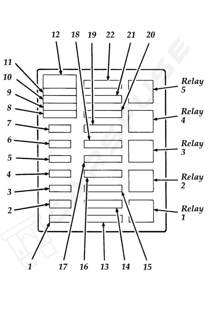
Power Distribution Box

| Fuse/CB/ Relay Loe. | Fuse Amp. Rating | Description |
| 1 | 20 amp | • Audio power |
| 2 | (15 amp) | • Fog lamps • 200 Amp alternator (Diesel ambulance only) |
| 3 | 30 amp | • Daytime running lamps(Canada only) • Headlamp flash-to-pass • Horn |
| 4 | 25 amp | • Trailer back-up lamps • Trailer running lamps |
| 5 | 15 amp | • Back-up lamps • Daytime running lamp module (DRL) (Canada only) • Oxygen sensor heater • Trailer battery charge relay |
| 6 | lO amp | • Trailer right-hand stop/ turn lamp |
| 7 | lO amp | • Trailer right-hand stop/ turn lamp |
| 8 | 30 ap maxi | • Injector driver module |
| 9 | 30 amp (Gas)20 amfJ (Diese ) | • Powertrain control system |
| 10 | 20 ap maxi | • Instrument panel fuses: 15, 18 • Starter relay coil |
| 11 | – | Not used |
| 12 | Diode | • Powertrain control system relay coil |
| 13 | 50 ap maxi | • Instrument panel fuses: 5, 9, 13 |
| 14 | – | Not used |
| 15 | 50 ap maxi | • Instrument panel fuses: 1, 7 • Power distribution box: fuse 5 |
| 16 | 20 ap maxi | • Fuel pump feed (Gas engine) |
| 17 | SO amp maxi | |
| 18 | 30 amp maxi | Trailer Battery Charge |
| 19 | 40 amp maxi | Headlamps |
| 20 | SO amp maxi | Instrument pane fuses: 4, 8, 12, 16 |
| 21 | 30 amp maxi | Trailer Brake Feed |
| 22 | 20 amp maxi (Gas) 30 amf1 (diesel) | Distribution pickup (Gas Engine) Fuel Line Heater (Diesel) Glow plug controller (Diesel) Ignition Coil (Gas Engine) Power Control System Relay Coil Thick Film Integrated (TFI) module (Gas Engine) |
| Relay 1 | Powertrain Control System | |
| Relay 2 | Fuel Pump (Gas Engine) Injector Driver Module (IDM Relay) (Diesel) | |
| Relay 3 | Horn | |
| Relay 4 | Trailer Tow Lamps |
1996 Ford F-250/350/450/550 Fuse Box Diagram
For the 1997 Ford Super Duty lineup (F-250, F-350, F-450, and F-550), the electrical system includes two main fuse boxes — the Instrument Panel Fuse Box and the Engine Compartment Fuse Box.
Instrument Panel Fuse Box

| Position | Amps | Description |
| 1 | 15 | Stop/turn lamps and turn indicators |
| 2 | 5 | Instrument cluster |
| 3 | 25 | Cigarette lighter |
| 4 | 5 | Power mirrors, autolamp, remote anti-theft/keyless entry, headlamp relay and parking lamp relay |
| 5 | 15 | Speed control, daytime running lamps, climate control blend door, backup lamps, A/C clutch coil |
| 6 | 5 | Brake-shift interlock, generic electronic module (GEM)/central timer module (CTM) and air suspension module |
| 7 | – | Not used |
| 8 | 5 | Radio, remote anti-theft/keyless entry, GEM module/CTM module |
| 9 | – | Not used |
| 10 | – | Not used |
| 11 | 30 | Wiper system |
| 12 | 5 | On-board diagnostic (OBD II) data link connector |
| 13 | 15 | Brake ON/OFF switch, rear anti-lock brake module and brake pressure switch |
| 14 | 15 | Interior lamps and accessory delay relay |
| 15 | 5 | GEM module/CTM module |
| 16 | 20 | High beam headlamps |
| 17 | – | Not used |
| 18 | 5 | Instrument illumination |
| 19 | 10 | Air bag diagnostic monitor, instrument cluster |
| 20 | 5 | GEM module/CTM module and powertrain control module (PCM) |
| 21 | 15 | Starter relay |
| 22 | 10 | Air bag diagnostic monitor and passenger air bag deactivate switch |
| 23 | 10 | 4WD clutch relay, electronic flasher, 4WD/2WD vacuum solenoids and trailer tow battery charge relay |
| 24 | 10 | I/P blower relay |
| 25 | 5 | 4WABS module and relay |
| 26 | 10 | Right low beam headlamp and DRL module |
| 27 | 5 | Foglamp relay |
| 28 | 10 | Left low beam headlamp |
| 29 | 5 | Autolamp, instrument cluster, transmission control indicator lamp and switch |
| 30 | 30 | Ignition coils and PCM relay |
| 31 | – | Not used |
Relays
| Position | Description |
| 1 | Interior lamps relay |
| 2 | Battery saver relay |
| 3 | Not used |
| 4 | One touch down relay |
| 5 | Accessory delay relay |
Power Distribution Box

| Position | Amps | Description |
| 1 | 20 | Trailer tow-back-up and tail lamps |
| 2 | 10 | Air bag diagnostic monitor |
| 3 | 15 | Power locks |
| 4 | 15 | Air suspension |
| 5 | 20 | Horn |
| 6 | 15 | Audio system |
| 7 | 15 | Parking and tail lamps |
| 8 | 30 | Headlamps |
| 9 | 15 | Daytime running lamps and fog lamps |
| 10 | 25 | Auxiliary power point |
| 11 | – | Not used |
| 12 | – | Not used |
| 13 | – | Not used |
| 14 | 60/20 | 4WABS/rear anti-lock brake |
| 15 | 50 | Air suspension compressor |
| 16 | 40 | Trailer tow battery charge and stop/turn lamps |
| 17 | 30 | 4WD transfer case shift motor and clutch |
| 18 | 30 | Driver power seat |
| 19 | 20 | Fuel pump |
| 20 | 50 | Instrument panel fuse panel ignition switch feed |
| 21 | 50 | Instrument panel fuse panel ignition switch feed |
| 22 | 50 | I/P fuse panel battery feed |
| 23 | 40 | I/P blower |
| 24 | 30 | PCM power |
| 25 | 30 | Power windows |
| 26 | – | Not used |
| 27 | – | Not used |
| 28 | 30 | Trailer tow electronic brake |
| 29 | – | Not used |
Tip: Some high-amperage fuses may look slightly different depending on the model year and trim. Always verify the fuse type before replacing.
Fuse Replacement Tips / Safety Precautions
- Always disconnect the negative battery terminal before removing fuses.
- Never replace a blown fuse with a higher amp rating — this can damage wiring or cause a fire.
- Use a fuse puller or needle-nose pliers for safety.
- Label replaced fuses for future reference.
Frequently Asked Questions (FAQs)
Why does the cigarette lighter (power socket) fuse keep blowing in my F-250?
The fuse usually blows because of:
Overload: Plugging in devices that use too much power (like air compressors or inverters).
Short circuit: Damaged or frayed wires touching metal parts.
Bad adapters: Cheap or faulty chargers causing excess current.
Wrong fuse: Using a fuse with lower amperage than Ford recommends.
Why does the radio fuse keep blowing in my F-250?
Common causes include:
Short circuit: Damaged or exposed wires touching metal parts.
Extra devices: Added accessories like amps drawing too much power.
Wrong fuse: Using a fuse with lower amperage than Ford recommends.
Faulty radio: A defect inside the radio causing high current draw.
Electrical issues: Problems like voltage spikes from a bad alternator.
Why does the fog light fuse keep blowing in my F-250?
Common reasons include:
Short circuit: Damaged or exposed fog light wiring touching metal parts.
Bad bulb: A faulty bulb drawing too much power.
Faulty switch: A worn or defective fog light switch causing current spikes.
Lighting mods: Added or modified lights (like LEDs) overloading the circuit.
Why does the tail light fuse keep blowing in my F-250?
Common causes include:
Short circuit: Damaged or frayed wires touching metal parts.
Bad or wrong bulb: Faulty or incompatible bulbs drawing too much power.
Faulty switch: A bad tail light switch causing current spikes.
Wrong fuse: Using a fuse with lower amperage than Ford recommends.
Why does the horn relay fail in my F-250?
Common reasons include:
Short circuit: Damaged wiring causing too much current flow.
Wear and tear: Relay contacts or coil wearing out from frequent use.
Voltage spikes: Electrical surges damaging the relay or related parts.

